Variable valve distribution camshaft of engine

A technology for engines and camshafts, applied to engine components, machines/engines, mechanical equipment, etc., can solve problems such as unsatisfactory, high cost, and poor reliability

Inactive Publication Date: 2021-06-11
YANSHAN UNIV
View PDF0 Cites 0 Cited by
  • Summary
  • Abstract
  • Description
  • Claims
  • Application Information

AI Technical Summary

Problems solved by technology

Among them, the multi-cam mechanical structure can only divide the speed change into 2 to 3 small ranges, and take the average speed to achieve the maximum efficiency in the small range, which cannot meet the needs of changing with the speed.
Although the electronic control method can realize the change of the fine speed range, the cost is high and the reliability is worse than that of the mechanical device.

Method used


Image

  • Variable valve distribution camshaft of engine
  • Variable valve distribution camshaft of engine
  • Variable valve distribution camshaft of engine

Examples


Embodiment Construction

[0013] In order to make the object, technical solution and advantages of the present invention more clear, the present invention will be further described in detail below in conjunction with the examples. The specific embodiments described here are only used to explain the present invention, not to limit the invention.

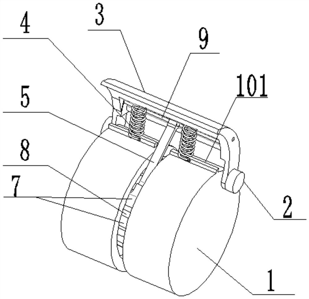
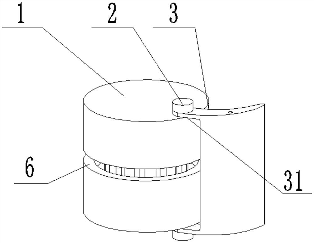
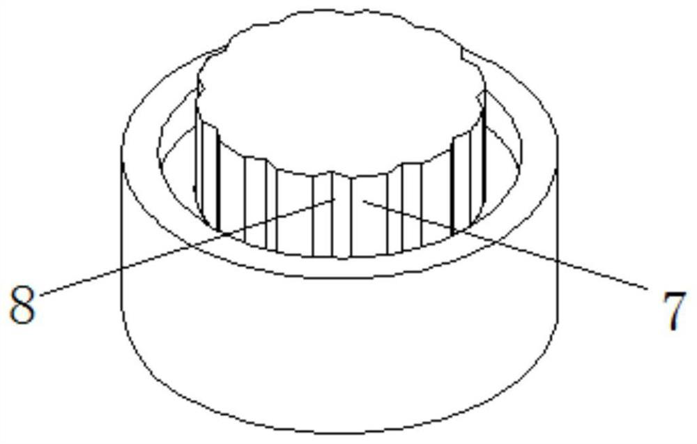
[0014] like Figure 1-Figure 3 As shown, a variable valve camshaft for an engine in this embodiment includes a cylindrical shaft 1, a fan-shaped steel plate 3, a spring 4, and a T-shaped connector 5. The outer wall of the cylindrical shaft 1 is provided with a circle along the circumference. An inverted T-shaped annular groove 6 has several ribs 7 evenly distributed axially along the cylinder axis, and axial grooves 8 are formed between two adjacent ribs 7; the upper and lower ends of the arc-shaped steel plate 3 are both The connecting plate 31 is fixedly connected, and the connecting plate 31 at the upper end and the lower end of the arc-shaped steel plate ...


PUM


Abstract

The invention discloses a variable valve distribution camshaft of an engine. The variable valve distribution camshaft comprises a cylindrical shaft, a fan-arc-shaped steel plate, a spring and a T-shaped connecting piece; a circle of inverted-T-shaped annular groove is formed in the outer wall of the cylindrical shaft along the circumference; multiple steps are arranged at the bottom of the inverted-T-shaped annular groove; the upper end and the lower end of the fan-arc-shaped steel plate are fixedly connected with connecting plates; the connecting plates at the upper end and the lower end of the fan-arc-shaped steel plate are rotationally connected to one side edge of the upper end face and one side edge of the lower end face of the cylindrical shaft through pins correspondingly; a T-shaped head of the T-shaped connecting piece is embedded into the inverted-T-shaped annular groove; the other end of the T-shaped connecting piece is rotationally connected to a pin shaft; the pin shaft is arranged in a concave face of the fan-arc-shaped steel plate in the axial direction of the fan-arc-shaped steel plate; two ends of the pin shaft are fixedly connected to the connecting plates; and the spring is connected between the cylindrical shaft and the fan-arc-shaped steel plate. The lift and the base circle of the camshaft are divided into the cylindrical shaft and the fan-arc-shaped steel plate, the height change of the curve of the fan-arc-shaped steel plate in the direction of a valve push rod is controlled by fully utilizing different centrifugal forces under different accelerations, the lift curve is changed, and the height of a throttle valve can be changed.

Description

technical field [0001] The invention relates to the field, in particular to an engine variable valve valve camshaft. Background technique [0002] When the gasoline engine is in different speed zones, the supply required to achieve the maximum efficiency is different. The valve lift of a traditional gasoline engine is fixed and invariable, which makes it impossible for the lift to make the engine respond well in both high-speed and low-speed areas. In order to make the engine obtain the required valve lift in both high-speed and low-speed areas, so as to improve the high-speed power and low-speed torque of the engine, variable valve lift technology is adopted. Existing mainstream technology adopts the method of multi-cam or electronic control. Among them, the multi-cam mechanical structure can only divide the speed change into 2 to 3 small ranges, and take the average speed to achieve the maximum efficiency in the small range, which cannot meet the needs of changing with t...

Claims


Application Information

Patent Timeline
Patent Type & Authority Applications(China)
IPC IPC(8): F01L1/047F01L13/00
CPCF01L1/047F01L13/0015
Inventor 唐先智武成晔黄星凯杨昊鑫
Owner YANSHAN UNIV
Why Eureka
Try Eureka