Wire plugging device
A wire insertion and cable technology, which is applied in the field of wire insertion devices, can solve the problems of inconvenient access or removal of cables, inability to quickly and accurately open or retract shrapnel and metal conductors, unstable connection between cables and metal conductors, etc.
- Summary
- Abstract
- Description
- Claims
- Application Information
AI Technical Summary
Problems solved by technology
Method used
Image


Examples
Embodiment 1
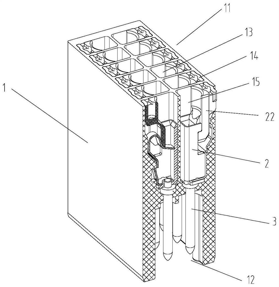
[0033] refer to Figure 1-Figure 10 As shown, this embodiment provides a wire insertion device, which mainly includes an insulating housing 1 , an elastic locking component 2 and a conductor 3 . Among them, the insulating housing 1 has a terminal 11 for connecting cables at the upper and lower ends according to the direction shown in the figure, and a plug-in terminal 12 for plugging with another electrical appliance or a mating terminal (female terminal block). Wherein, the terminal 11 has a plurality of wiring ports 13, the wiring ports 13 are inserted for the cable wire 4, and an auxiliary interface 14 is set beside each wiring opening 13, and the auxiliary interface 14 can be inserted for auxiliary tools, and the wiring port 13 and the auxiliary interface 14 A wiring cavity 15 is formed below, and the elastic locking assembly 2 is arranged in the wiring cavity 15 to compress the inserted cable 4 or loosen the cable 4, so that the cable 4 is constrained in the elastic locki...
Embodiment 2
[0045] refer to Figure 11 As shown, similar to the elastic locking assembly 2 in Embodiment 1, this embodiment provides another elastic locking assembly 2, which is applied to the wire insertion device, and its structure is basically the same as that of the elastic locking assembly 2 in Embodiment 1. , the difference is that the structural form of the mounting part 231 of the shrapnel 23 is different:
[0046] In this embodiment, the appearance of the main body of the shrapnel mounting part 231 is "L" shaped, and the side 233 of the mounting part 231 is provided with a first matching hole 24, wherein a second matching hole 25 is provided at a corresponding position inside the wiring cavity 15, and the cover assembly 26 Through the first matching hole 24 and the second matching hole 25 , the elastic piece 23 is fixed in the wiring cavity 15 . The cover assembly 26 and the wiring cavity 15 may be fastened by providing positioning pins on the cover assembly 26, or in other ways...
Embodiment 3
[0048] refer to Figure 12-Figure 13 As shown, similar to the elastic locking assembly 2 in Embodiment 1, this embodiment provides another elastic locking assembly, which is applied to the wire insertion device, and its structure is basically the same as that of the elastic locking assembly 2 in Embodiment 1. The difference is that the structure of the conductive seat 21 and the conductor 3 is different:
[0049] In this embodiment, the conductive seat 21 and the conductor 3 are integrally formed, and the two are collectively called the locking conductive part. The upper part of the locking conductive part is a "["-shaped sheet body, and the two side plates 216 are fixedly arranged on both sides of the bottom plate 215. The three form a semi-enclosed chamber, and the upper ends of the two side plates 216 are provided with guide grooves 217, and the operating member can perform linear reciprocating sliding movement in the guide grooves 217; the conductor 3 is located below the ...
PUM
 Abstract
Description
Claims
Application Information
 - Generate Ideas
- Intellectual Property
- Life Sciences
- Materials
- Tech Scout
- Unparalleled Data Quality
- Higher Quality Content
- 60% Fewer Hallucinations
Browse by: Latest US Patents, China's latest patents, Technical Efficacy Thesaurus, Application Domain, Technology Topic, Popular Technical Reports.
© 2025 PatSnap. All rights reserved.Legal|Privacy policy|Modern Slavery Act Transparency Statement|Sitemap|About US| Contact US: help@patsnap.com