Turbulent gas generating unit and honeycomb type turbulent gas generating device

A technology of gas generating unit and gas generating device, applied in the field of turbulent gas generating unit and generating device, turbulent gas generating device

Pending Publication Date: 2021-06-08
刘森
View PDF0 Cites 1 Cited by
  • Summary
  • Abstract
  • Description
  • Claims
  • Application Information

AI Technical Summary

Problems solved by technology

[0004] In order to solve the technical problem of how to improve the dust removal efficiency, the present invention designs a turbulent gas generating unit and a honeycomb turbulent gas generating device

Method used


Image

  • Turbulent gas generating unit and honeycomb type turbulent gas generating device
  • Turbulent gas generating unit and honeycomb type turbulent gas generating device
  • Turbulent gas generating unit and honeycomb type turbulent gas generating device

Examples


Embodiment Construction

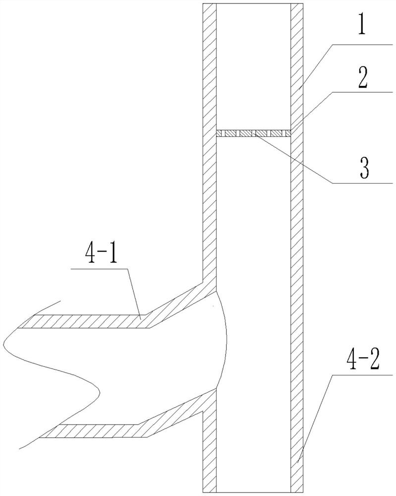
[0025] see figure 1 , a turbulent gas generating unit, the key is: the structure of the turbulent gas generating unit includes a vertically placed cylinder 1 with a top liquid storage port and a bottom liquid drop port 4-2, an air supply branch 4-1, and the partition plate 2 arranged in the cylinder 1 and above the air supply branch 4-1, the air supply branch 4-1 is connected with the cylinder 1 to form a three-way structure 4, and a partition 2 is distributed with a A set of through holes 3 for amplifying the wind speed.

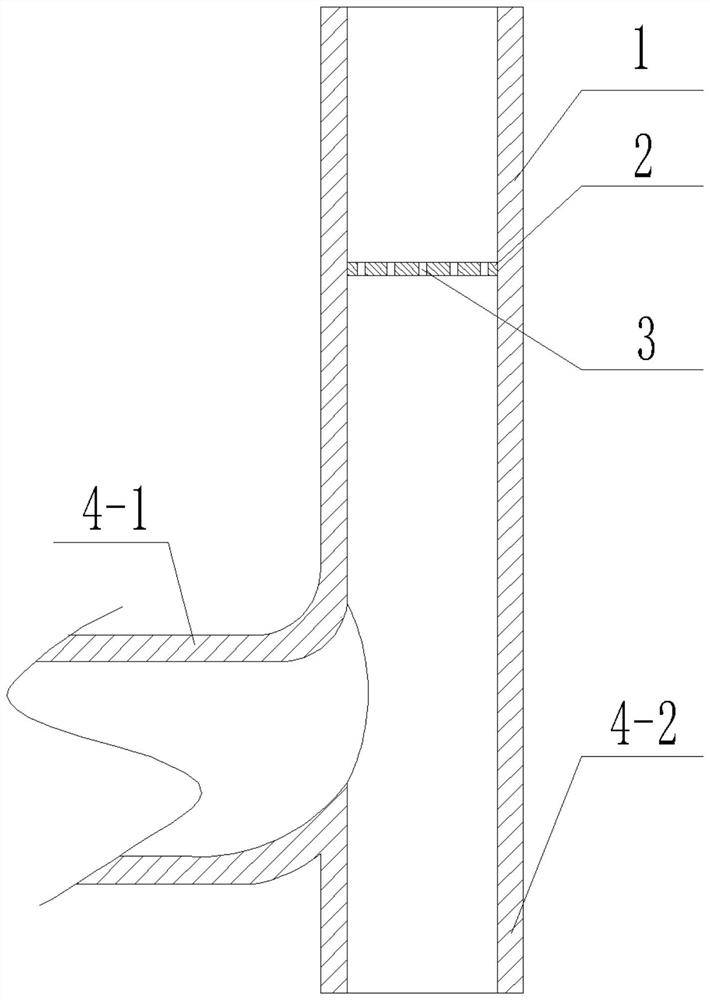
[0026] see figure 2 , in order to make all the wind sent by the fan blow upwards, the connection between the air supply branch 4-1 and the cylinder 1 is an inclined upward connection structure or a curved upward connection structure.

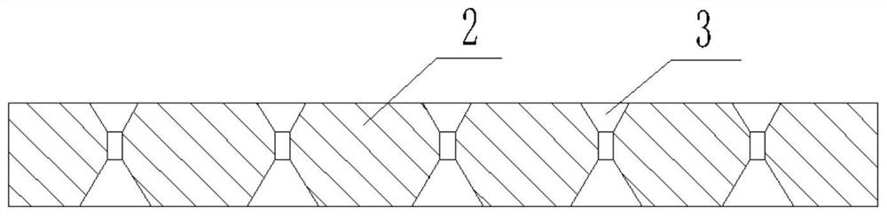
[0027] see image 3 and Figure 4 , the through hole 3 is an hourglass-shaped structure with a large upper and lower diameter and a small middle diameter.

[0028] see Figure 5 and Image 6 , the through-holes 3 are ...


PUM


Abstract

The invention discloses a turbulent gas generating unit and a honeycomb type turbulent gas generating device, and solves the technical problem of how to improve the dust removal efficiency. The key is that a turbulent gas generating unit structurally comprises a barrel which is vertically arranged and provided with a top liquid storage opening and a bottom liquid falling opening, an air supply branch and a partition plate which is arranged in the barrel and located above the air supply branch; the air supply branch and the barrel are communicated to form a three-way structure, and a group of through holes used for increasing the air speed are distributed in the partition plate. The dust removal device has the beneficial effect that the dust removal efficiency is greatly improved. In addition, the work of the device belongs to intermittent filtration, after liquid waves of the dust removal liquid fully suck smoke dust, the fan is stopped, and the dust removal liquid flows back downwards under the action of gravity due to the absence of upward wind thrust. In the backflow process, clear dust removal liquid can be directly recycled in a filtering mode for subsequent continuous use, the desilting time is shortened, water resources are greatly saved, and circulating work can be achieved only through a small number of water sources.

Description

technical field [0001] The invention belongs to the technical field of flue gas transportation, and relates to a turbulent gas generating unit and a generating device, in particular to a turbulent gas generating device for electro-hydraulic dust removal of flue gas. Background technique [0002] At present, in the technical field of flue gas dedusting, the commonly used dedusting methods are electric dust removal, mechanical dust removal, filter dust removal, and washing dust removal. Among them, washing dust removal belongs to wet dust removal, and the rest methods are dry dust removal. The advantage of wet dedusting is that it can absorb the dust that is easily soluble in the dedusting liquid, but the disadvantage is that the deposited silt is not easy to recycle, and at the same time, the removal effect of the soot that is not easy to honor the dedusting liquid is not good. There is also a spray dust removal method. The dust reduction effect of the spray method is better...

Claims


Application Information

Patent Timeline
Patent Type & Authority Applications(China)
IPC IPC(8): B01D47/06
CPCB01D47/06
Inventor 刘森
Owner 刘森
Why Eureka
Try Eureka