Double-balloon injection catheter instrument for blood vessel thrombolysis
An injection catheter and double balloon technology, applied in the direction of balloon catheters, catheters, coatings, etc., can solve the problems of low embolus dissolution rate and inability to effectively improve the efficiency of thrombolysis, so as to avoid hemorrhagic complications and increase blood pressure. The effect of high contact rate
- Summary
- Abstract
- Description
- Claims
- Application Information
AI Technical Summary
Problems solved by technology
Method used
Image
Examples
Embodiment 1
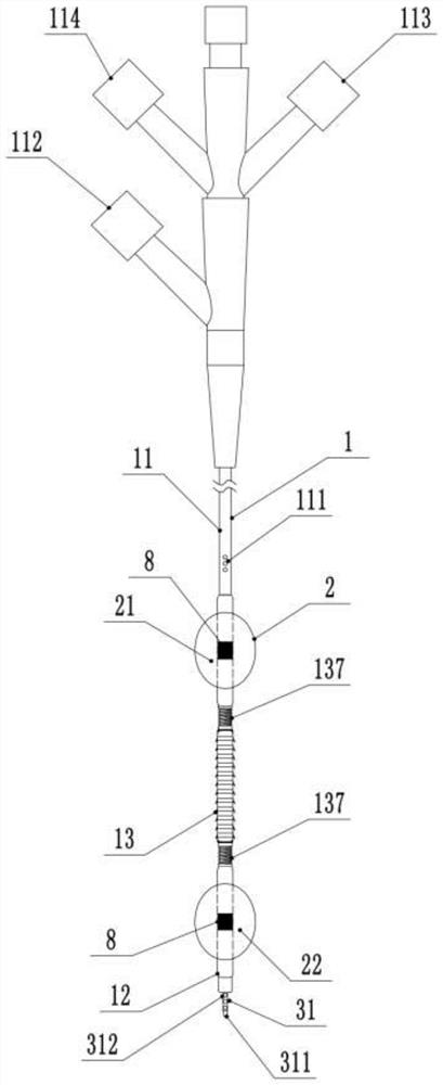
[0056] figure 1 It is a schematic structural diagram of a double-balloon injection catheter device for vascular thrombolysis provided according to a preferred embodiment of the present invention. In this drawing, the distal end refers to the lower end, and the proximal end refers to the upper end.
[0057] Such as figure 1 , 2 , 4, the double-balloon injection catheter apparatus for vascular thrombolysis of the present invention includes an injection catheter 1, a balloon 2 that is sheathed on the outside of the injection catheter 1 and a lumen 3 that is arranged on the inside of the injection catheter 1,
[0058] Such as figure 1 As shown, the injection catheter 1 includes a first catheter segment 11, a second catheter segment 12 and a drug injection catheter segment 13 connected between the first catheter segment 11 and the second catheter segment 12.
[0059] Such as Figure 9 As shown, the drug injection catheter section 13 includes: a first connecting piece 131 and a...
Embodiment 2
[0073] This embodiment is basically the same as Embodiment 1, the difference is:
[0074] Such as figure 2 As shown, the drug injection catheter section 13 also includes two bellows 137, the bellows 137 are arranged on the first catheter section 11 between the first balloon 21 and the first connecting piece 131, and / or the second balloon 22 On the second conduit segment 12 between the second connecting piece 132, it is used to buffer the impact force generated by the electrification deformation film 133 when the power is turned on and off. Since the buffer bellows 137 is added in the axial direction, it can make the electrification deformation The membrane 133 moves the position of the balloon 2 when it expands and contracts in the axial direction after being energized.
Embodiment 3
[0076] This embodiment is basically the same as Embodiment 2, the difference is:
[0077] Such as figure 2 As shown, the outflow hole 312 is provided on the radially outer periphery of the tip portion 311. When the injection catheter 1 passes through the embolus 5, accumulation is likely to occur at the axial end of the tip portion 311, which may cause blockage. In order to avoid this situation, it is preferable to open the outlet hole 312 on the radial outer periphery of the tip portion 311 .
PUM
| Property | Measurement | Unit |
|---|---|---|
| length | aaaaa | aaaaa |
| length | aaaaa | aaaaa |
| thickness | aaaaa | aaaaa |
Abstract
Description
Claims
Application Information
 - R&D
- Intellectual Property
- Life Sciences
- Materials
- Tech Scout
- Unparalleled Data Quality
- Higher Quality Content
- 60% Fewer Hallucinations
Browse by: Latest US Patents, China's latest patents, Technical Efficacy Thesaurus, Application Domain, Technology Topic, Popular Technical Reports.
© 2025 PatSnap. All rights reserved.Legal|Privacy policy|Modern Slavery Act Transparency Statement|Sitemap|About US| Contact US: help@patsnap.com


