
Camera module structure and electronic equipment

A camera module and imaging module technology, applied in branch equipment, telephone structure, TV and other directions, can solve the problems of unstable image quality, inability to automatically focus, complicated operation when taking pictures, etc., and achieve high popularity and low cost. Effect

Pending Publication Date: 2021-06-04
CONVERGENCE TECH CO LTD
View PDF1 Cites 1 Cited by
  • Summary
  • Abstract
  • Description
  • Claims
  • Application Information

AI Technical Summary

Problems solved by technology

[0009] Aiming at at least one of the above defects or improvement needs of the prior art, the present invention provides a camera module structure and electronic equipment, thereby overcoming the difficulties encountered in the field of miniaturized microscopic imaging, and further solving the problem of existing electronic devices. The equipment can not solve the problem of automatic focus in the field of macro, super macro or microscopic imaging, which leads to complex operation and unstable image quality when taking pictures

Method used


Image

  • Camera module structure and electronic equipment
  • Camera module structure and electronic equipment
  • Camera module structure and electronic equipment

Examples


Embodiment Construction

[0040] In order to make the object, technical solution and advantages of the present invention clearer, the present invention will be further described in detail below in conjunction with the accompanying drawings and embodiments. It should be understood that the specific embodiments described here are only used to explain the present invention, not to limit the present invention. In addition, the technical features involved in the various embodiments of the present invention described below can be combined with each other as long as they do not constitute a conflict with each other. The present invention will be further described in detail below in combination with specific embodiments.

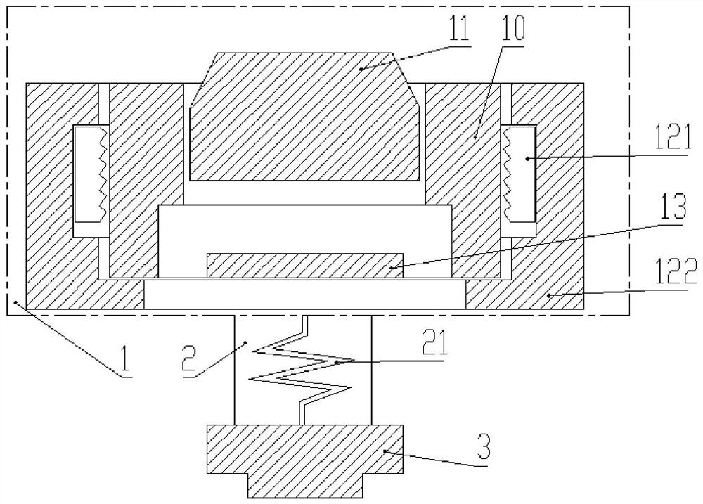
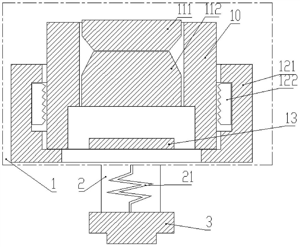
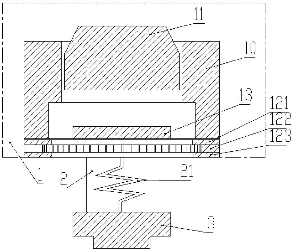
[0041] As a preferred embodiment of the present invention, such as Figure 1-6 As shown, the present invention provides a camera module structure and electronic equipment containing it, including: an imaging module and an axial overall focusing module.

[0042] The imaging module includes ...


PUM


Abstract

The invention discloses a camera module structure and electronic equipment comprising the same, and the camera module structure comprises an imaging module which comprises a lens part and a photoelectric sensor part, and the lens part and the photoelectric sensor part are arranged at a fixed distance; and the axial integral focusing module is connected with the imaging module, and the whole of the lens part and the photoelectric sensor part is axially moved for focusing. By fixing the distance between the lens and the photoelectric sensor, the focusing stroke can be greatly improved, object image conjugation can be realized in the allowable stroke of the motor, high imaging quality is maintained, the objective of simplifying microscopic imaging operation is further realized, and the device can be combined with electronic equipment and has a huge prospect in medical treatment, science popularization education and public health.

Description

technical field [0001] The invention belongs to the technical field of electronic equipment, especially the imaging technology of electronic equipment, and in particular relates to a camera module structure and electronic equipment. Background technique [0002] The microscopic imaging system can realize high-magnification imaging to meet people's needs for observing the microscopic world. The imaging of the traditional microscope system is based on the multi-lens combination structure of the objective lens and the tube lens, or the objective lens and the eyepiece lens. In order to achieve magnified imaging, splicing and cooperation are carried out. The overall system is too large and too long. Laboratories, quality inspection institutes and other places. [0003] The miniaturized microscopic system is a high demand point in the current microscopic imaging industry. The demand point is that if the miniaturized microscopic system is realized, the application scenarios and ap...

Claims


Application Information

Patent Timeline
IPC IPC(8): H04N5/225H04N5/232H04M1/02
CPCH04M1/0264H04N23/58H04N23/54H04N23/57H04N23/55H04N23/67
Inventor 胡庆磊黄凯李宁李梦婷吴梓杰
Owner CONVERGENCE TECH CO LTD
Learn More