Automatic bar microscopic examination equipment

A bar and microscopic inspection technology, applied in the field of laser bar appearance inspection, can solve the problems of high labor intensity, low inspection efficiency, and difficulty in mass production, and achieve the effect of improving inspection efficiency.

Active Publication Date: 2021-06-04
SUZHOU EVERBRIGHT PHOTONICS CO LTD +1
View PDF7 Cites 1 Cited by
  • Summary
  • Abstract
  • Description
  • Claims
  • Application Information

AI Technical Summary

Problems solved by technology

[0003] In the current production process, the appearance inspection is generally done manually, but the inspection work is labor-intensive, which easily causes visual fatigue, leads to low inspection efficiency, and is difficult to achieve large-scale production

Method used


Image

  • Automatic bar microscopic examination equipment
  • Automatic bar microscopic examination equipment
  • Automatic bar microscopic examination equipment

Examples


Embodiment

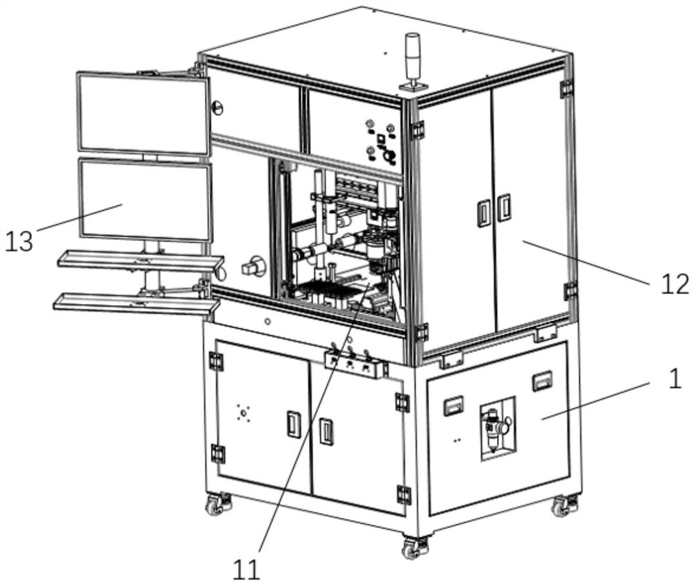
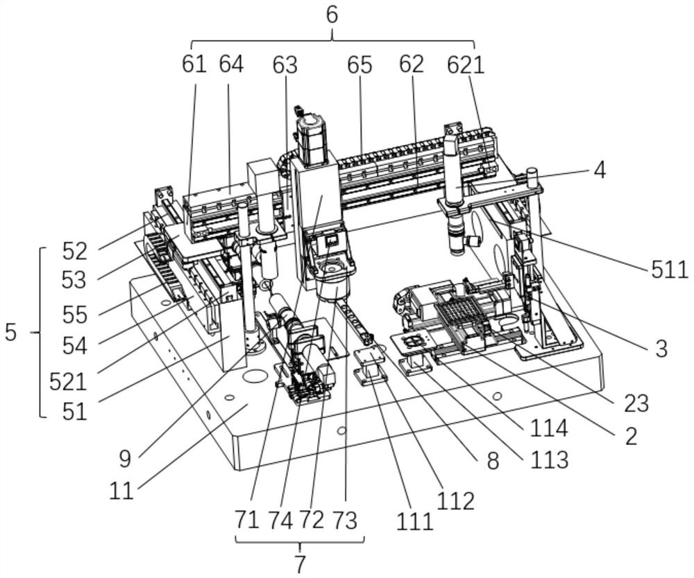
[0050] refer to figure 1 and figure 2 , the present application provides a bar automatic microscope inspection equipment, which includes a lower frame 1 and an upper frame 12, and a work platform 11 is installed between the lower frame 1 and the upper frame 12. The work platform 11 is a marble platform. The work platform 11 is provided with a loading tray 23, a first loading and unloading assembly 3, a second loading and unloading assembly 8 and a camera detection assembly 9. The work platform 11 is also provided with a The Tray tray transfer assembly 2 for moving the Tray tray 23 and the second loading and unloading assembly moving device for driving the second loading and unloading assembly 8 to move, wherein:

[0051] Feeding Tray dish 23, is used for depositing several bars to be tested;

[0052] The first loading and unloading assembly 3 is used to take the bar to be tested in the feeding tray 23, and put the detected bar back into the feeding tray 23;

[0053] The se...


PUM


Abstract

The invention discloses automatic bar microscopic examination equipment which comprises a working platform deck; a feeding tray, a first feeding and discharging assembly, a second feeding and discharging assembly and a camera detection assembly are arranged on the working platform deck; a tray transferring assembly and a second feeding and discharging assembly moving device are further arranged on the working platform deck; the feeding tray is used for storing a to-be-detected bar; the first feeding and discharging assembly is used for taking the to-be-detected bar and putting the detected bar back to the feeding tray; the second feeding and discharging assembly is used for taking the to-be-detected bar on the first feeding and discharging assembly and transferring the to-be-detected bar to a detection area of the camera detection assembly; the detected bar is transferred to the first feeding and discharging assembly; the camera detection assembly is used for detecting the to-be-detected bar; and the tray transferring assembly is used for driving the feeding tray to move so that the to-be-detected bar on the feeding tray can reach the taking area of the first feeding and discharging assembly. The equipment has the effects of improving the bar detection efficiency and being suitable for large-scale production of bars.

Description

technical field [0001] The application relates to the technical field of laser bar appearance inspection, and in particular to an automatic bar inspection equipment. Background technique [0002] In the laser semiconductor industry, after the wafer is dissociated into bars, strict visual inspection is required on the bars, mainly on the P side, AR side and HR side (where the P side is the side of the bar, and the AR side and the The HR surface is the end surface of the bar) for damage and pollution. [0003] In the current production process, the appearance inspection is generally done manually, but the inspection work is labor-intensive, which easily causes visual fatigue, leads to low inspection efficiency, and is difficult to achieve large-scale production. Contents of the invention [0004] Therefore, the purpose of this application is to provide a kind of bar automatic mirror inspection equipment, which has the effect of improving the efficiency of bar inspection. Th...

Claims


Application Information

Patent Timeline
Patent Type & Authority Applications(China)
IPC IPC(8): G01N21/88B65G47/74B65G47/91
CPCG01N21/88B65G47/912B65G47/74
Inventor 潘华东胡凯周立李青龙赵长福
Owner SUZHOU EVERBRIGHT PHOTONICS CO LTD
Why Eureka
Try Eureka