
Method of controlling vehicle emissions

A vehicle and parameter technology, applied in electrical control, engine control, fuel injection control, etc., to solve problems such as not covering theoretical driving styles

Active Publication Date: 2021-06-01
DELPHI INT OPERATIONS LUXEMBOURG S A R L
View PDF4 Cites 1 Cited by
  • Summary
  • Abstract
  • Description
  • Claims
  • Application Information

AI Technical Summary

Problems solved by technology

Although this approach greatly limits the CO 2 penalty, but it also poses some legal risks as it does not cover all theoretical driving styles

Method used


Image

  • Method of controlling vehicle emissions
  • Method of controlling vehicle emissions
  • Method of controlling vehicle emissions

Examples


Embodiment Construction

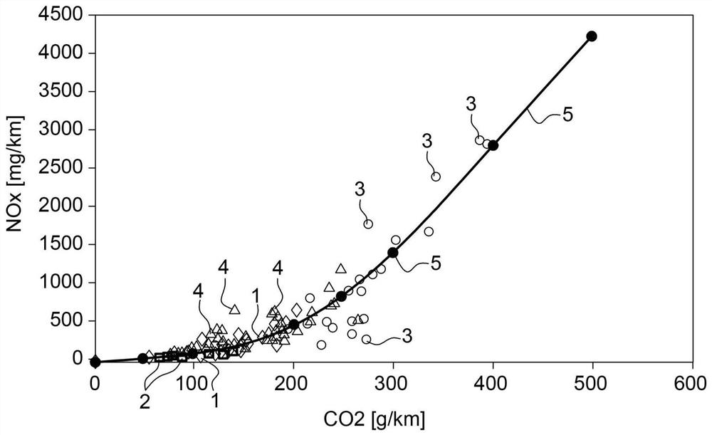
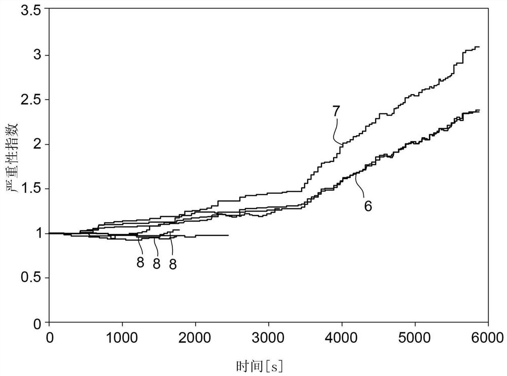
[0031] In one aspect, the severity of driving style is analyzed in the engine control software and can be analyzed by providing NO x output to grade the severity of driving style, and this analysis is used to then automatically adjust the calibration and control of engine output online such that [NO x ] / [CO 2 , PM, urea consumption] tradeoffs can be made towards lower NO when required x value shift (to prevent exceeding NO in case of aggressive driving style x emission limits).

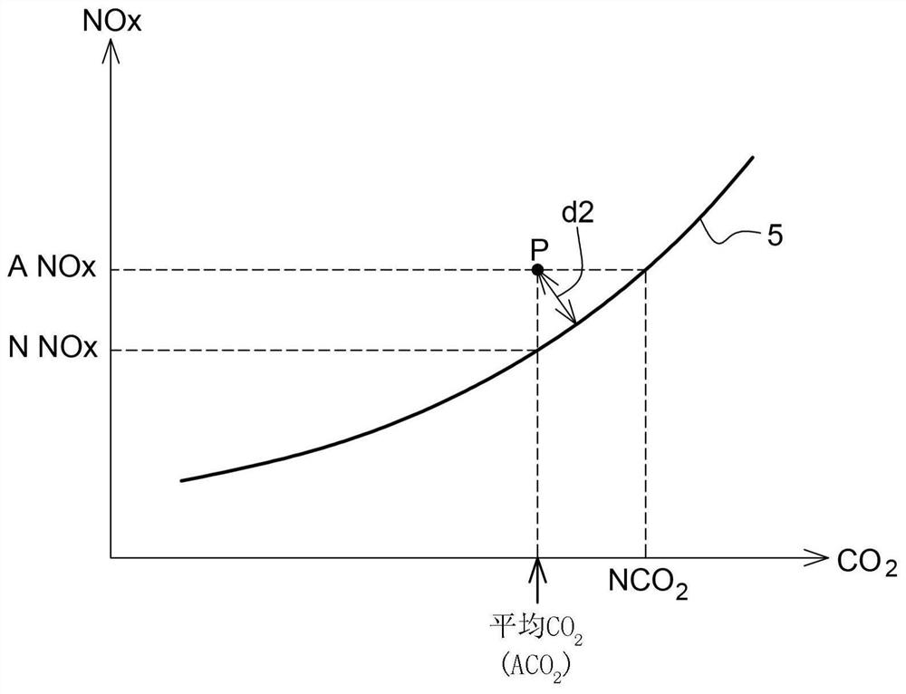
[0032] In summary, one aspect of the invention involves determining the NO x output with power output or CO 2 output associated driving parameters (or CO 2 output with power output or NO x output correlation), and effectively determine how far this combined parameter is from a calibration curve or a calibration map, for example to provide a severity index. How far the severity index or combined parameter is from the reference curve is then used to control one or more engine parameters (eg EGR / u...


PUM


Abstract

A method of controlling a vehicle engine comprises a) determining at least two engine operational parameters selected from the following parameters: i) CO2 output, ii) power output iii) NOx output; b) averaging the values of said two parameters during a driving window; c) providing a nominal reference curve relating said two of the following engine parameters; d) comparing the result from step b) with said reference curve to determine a measure of how far the parameter averages obtained from step b) are from the reference curve; e) adjusting control of one or more engine systems dependent on the result of step d).

Description

technical field [0001] The present application relates to a method of controlling vehicle emissions and applies to both gasoline and diesel engines. It applies particularly, but not exclusively, to engines with exhaust gas recirculation (EGR). Background technique [0002] With the introduction of Real Driving Emissions (RDE) to the Euro 6d regulation, passenger cars must meet certain emission limits under wider conditions than in the past. Under Euro 6b and earlier regulations, engine manufacturers were required to comply with emission limits for the mild pseudo-steady state NEDC cycle. Engine calibration mostly focuses on this. [0003] Thus, under random driving conditions (non-cycling) Euro 6d vehicles are cleaner than earlier versions of the regulation, especially with regard to NO for diesel vehicles x emission. [0004] Control NO of RDE x Emissions require extensive use of all available devices provided by engine H / W and aftertreatment systems. However, reducin...

Claims


Application Information

Patent Timeline
IPC IPC(8): F02D41/14
CPCF02D2250/36F02D41/1462F02D41/1479F02D41/1491F02D41/1406F02D41/1452F01N2900/1402F01N2900/08F01N2900/0418F01N3/208F02B37/12Y02A50/20F02D29/02F01N3/02F01N3/08F01N3/0871F02D41/0007F02D41/0047F02D41/30
Inventor M·帕门迪尔J·施密特
Owner DELPHI INT OPERATIONS LUXEMBOURG S A R L
Learn More