
Method for measuring thickness of boundary layer

A technology for thickness measurement and boundary layer, which is applied in the field of aerodynamics in the aerospace industry, and can solve problems such as large measurement errors and limited number of measurement points

Active Publication Date: 2021-06-01
INST OF HIGH SPEED AERODYNAMICS OF CHINA AERODYNAMICS RES & DEV CENT
View PDF5 Cites 2 Cited by
  • Summary
  • Abstract
  • Description
  • Claims
  • Application Information

AI Technical Summary

Problems solved by technology

However, the number of measuring points in this measurement method is very limited, and the distance between the total pressure detection tube and the static pressure probe is relatively short, there is a certain degree of flow interference, and the measurement error is relatively large

Method used


Image

  • Method for measuring thickness of boundary layer
  • Method for measuring thickness of boundary layer
  • Method for measuring thickness of boundary layer

Examples


Embodiment 1

[0045] Embodiment 1 of the present invention is the measurement of the thickness of the boundary layer on the side wall of a certain transonic wind tunnel test section. The thickness of the boundary layer is measured by the method proposed by the present invention based on the moving pitot tube and binocular vision distance measurement. The specific process is as follows:

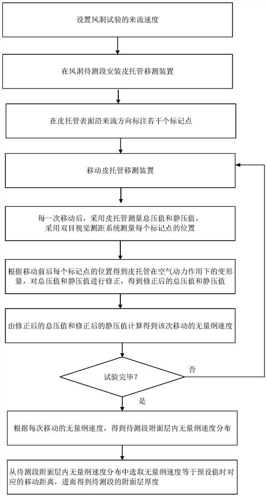
[0046] Step 1) Fix the pitot tube on the bracket on the side wall of the wind tunnel test section, and the bracket can move freely perpendicular to the side wall of the test section.

[0047] A pitot tube bracket is processed and installed at the measurement position of the boundary layer thickness on the side wall of the wind tunnel test section. The support can move freely in the direction perpendicular to the side wall by motor or other means.

[0048] Step 2) Paste or spray a plurality of special marking points for binocular vision ranging on the pitot tube surface along the flow direction.

[0049] 3-...


PUM


Abstract

The invention discloses a method for measuring the thickness of a boundary layer, and themethod is realized based on a pitot tube moving and measuring device and a double-sided visual ranging system. The method comprises the following steps: installing the pitot tube moving and measuring device at a to-be-measured section of a wind tunnel, wherein the pitot tube moving and measuring device comprises a bracket and a pitot tube fixed on the bracket; marking a plurality of mark points on the surface of the pitot tube in the incoming flow direction; moving the pitot tube moving and measuring device; after each movement, measuring a total pressure value and a static pressure value, and measuring the position of each mark point; according to the position of each mark point before and after movement, obtaining the deformation of the pitot tube under the action of aerodynamic force, correcting the total pressure value and the static pressure value, and obtaining the corrected total pressure value and the corrected static pressure value; calculating to obtain a dimensionless speed of the movement; according to the dimensionless speed of each movement, obtaining dimensionless speed distribution in the boundary layer; and selecting a corresponding movement distance when the dimensionless speed is equal to a preset value, and further obtaining the boundary layer thickness of the to-be-measured section.

Description

technical field [0001] The invention relates to the technical field of aerodynamics in the aerospace industry, in particular to a method for measuring the thickness of a boundary layer. Background technique [0002] The boundary layer is a thin flow layer in which the viscous force close to the object surface in the fluid flow around it is not negligible, also known as the flow boundary layer or boundary layer. This concept was first proposed by Prandtl, the founder of modern fluid mechanics, in 1904. In the boundary layer, the fluid close to the object surface completely adheres to the object surface, and the flow velocity is zero; from the object surface along the normal direction outward, the fluid velocity rapidly increases to the local free flow velocity. The development, transition, and separation of the boundary layer have a very important impact on the aerodynamic characteristics of advanced aircraft and the quality of the flow field in large-scale production wind t...

Claims


Application Information

Patent Timeline
IPC IPC(8): G01B11/02G01B11/26
CPCG01B11/02G01B11/26Y02T90/00
Inventor 吴继飞李国帅徐来武罗新福李阳
Owner INST OF HIGH SPEED AERODYNAMICS OF CHINA AERODYNAMICS RES & DEV CENT
Learn More