Reinforcement cage hoisting mechanism and reinforcement cage conveying line

A technology of rib cage and driving mechanism, which is applied in the direction of transportation and packaging, building construction, load hanging components, etc. It can solve the problems of inability to guarantee the hook and unhook, and achieve short transportation distance, compact layout and high efficiency. Effect

Pending Publication Date: 2021-06-01
周兆弟
View PDF0 Cites 2 Cited by
  • Summary
  • Abstract
  • Description
  • Claims
  • Application Information

AI Technical Summary

Problems solved by technology

However, it is found in the actual production process that if the steel cage lifting device of the above structure is adopted, when the steel cage is transported to the hook lifting place and the predetermined position, the steel cage rolls or falls to the predetermined position from the conveying structure, due to Due to inertia, the steel cage continues to move forward, and it will inevitably shake or turn over. At this time, the circumferential position of the main reinforcement of the reinforcement cage changes relative to the ideal predetermined position, and it cannot be guaranteed that the hook must be between the two main reinforcements. , the position of the hook needs to be adjusted to a certain extent to be able to effectively lift the reinforcement cage, and it is very likely that the hook cannot be unhooked when unhooked

Method used


Image

  • Reinforcement cage hoisting mechanism and reinforcement cage conveying line
  • Reinforcement cage hoisting mechanism and reinforcement cage conveying line
  • Reinforcement cage hoisting mechanism and reinforcement cage conveying line

Examples


Embodiment Construction

[0028] In order to facilitate the understanding of the technical solution of the present invention, the following describes in detail in conjunction with the accompanying drawings and specific embodiments.

[0029] In this article, terms such as "upper, lower, inner, outer" are established based on the positional relationship shown in the drawings, and the corresponding positional relationship may also change accordingly depending on the drawings. It is understood as an absolute limitation on the scope of protection; moreover, relative terms such as "first" and "second" are only used to distinguish one from another component with the same name, and do not necessarily require or No such actual relationship or order between these components is implied.

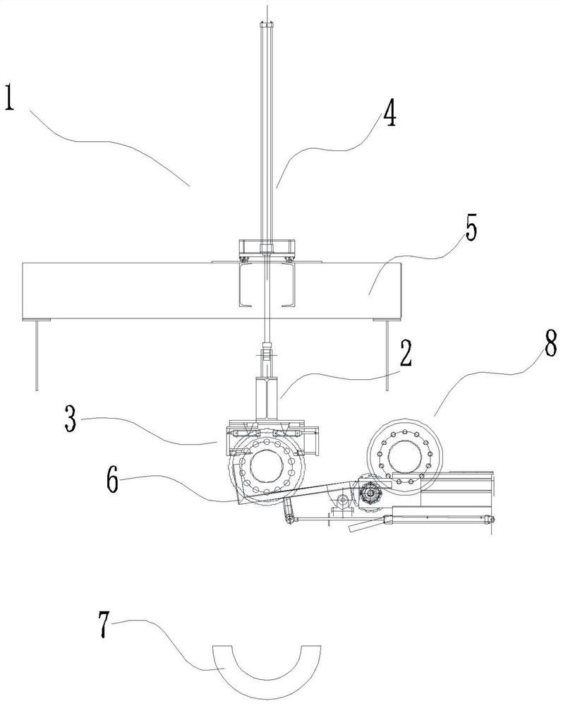
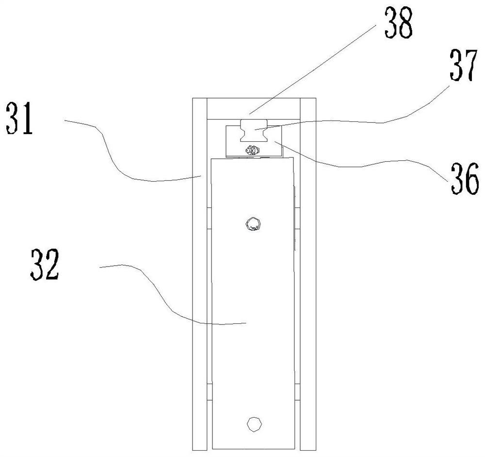
[0030] Please refer to Figure 1-3 , figure 1 The structural diagram of the hoisting part of the cage hoisting mechanism provided by the present invention, figure 2 It is the structural diagram of the cage holding device, ...


PUM


Abstract

The invention discloses a reinforcement cage hoisting mechanism and a reinforcement cage conveying line. The reinforcement cage hoisting mechanism comprises a cross beam capable of moving up and down, and a reinforcement cage retaining device connected to the cross beam. The lower part of the reinforcement cage retaining device is provided with an open slot capable of at least partially accommodating the reinforcement cage. A first bolt and a second bolt which are inserted into a reinforcement cage and can clamp the reinforcement cage are respectively arranged on two longitudinal sides of the lower part of the open slot. The first bolt and the second bolt can reciprocate in the longitudinal direction and are oppositely arranged or arranged in a staggered mode in the transverse direction. By the adoption of the structure, due to the gravity of the reinforcement cage retaining device and an arc-shaped structure of surfaces of upper reinforcing steel bars on the reinforcement cage, the reinforcement cage is forced to rotate or the reinforcement cage retaining device slides along the surfaces of the upper reinforcing steel bars on the reinforcement cage, then the upper surface of the reinforcement cage is completely contained in the open slot, the reinforcement cage retaining device can conveniently position the reinforcement cage and allow the bolts to be inserted during hoisting, and the cage grabbing reliability is improved; and meanwhile, the bolts are longitudinally and horizontally inserted, so that the reliability of cage grabbing and unhooking is ensured.

Description

technical field [0001] The invention belongs to the technical field of prefabricated component manufacturing equipment, and relates to a tendon cage lifting mechanism and a tendon cage conveying line. Background technique [0002] Precast concrete piles are pile foundation materials widely used in the construction industry, and steel cages are an indispensable part in the production process of precast concrete piles. The steel cages are mainly processed by the combination of main bars and spiral bars or stirrups. It needs to be hoisted and transported to the designated location by a hoisting device, but due to the long length and heavy weight of the steel cage, it is difficult to transport, and the steel cage is usually lifted by a hook. For example, a steel cage lifting device disclosed in the prior art is connected with a hook for transportation at the bottom of the suspension beam, and the hook is turned over under the action of the driving mechanism, stretches into the s...

Claims


Application Information

Patent Timeline
Patent Type & Authority Applications(China)
IPC IPC(8): B66C1/10B66C1/66E04G21/16
CPCB66C1/10B66C1/66E04G21/16
Inventor 周兆弟
Owner 周兆弟
Why Eureka
Try Eureka