Plastic bottle waste recycling and extruding device
A technology of extrusion device and plastic bottle, applied in the field of plastic bottle waste recycling extrusion device, can solve the problems of multi-space, waste of garbage storage space, low transportation volume, etc., and achieve the effect of avoiding horizontal transmission
- Summary
- Abstract
- Description
- Claims
- Application Information
AI Technical Summary
Problems solved by technology
Method used
Image
Examples
specific Embodiment approach 1
[0037] Combine below Figure 1-15 Describe this embodiment, a plastic bottle recycling extrusion device, including a conveyor belt mechanism 1, a secondary extrusion mechanism 2, a straightening mechanism 3, a bottle adaptation mechanism 4, a power mechanism 5 and a fork hole mechanism 6, the The secondary extrusion mechanism 2 is fixedly installed on the conveyor belt mechanism 1, the straightening mechanism 3 is fixedly installed on the conveyor belt mechanism 1, the bottle body adapting mechanism 4 is fixedly installed on the conveyor belt mechanism 1, and the power mechanism 5 is fixedly connected with the bottle body adapting mechanism 4 , The fork hole mechanism 6 is fixedly installed on the power mechanism 5 .
specific Embodiment approach 2
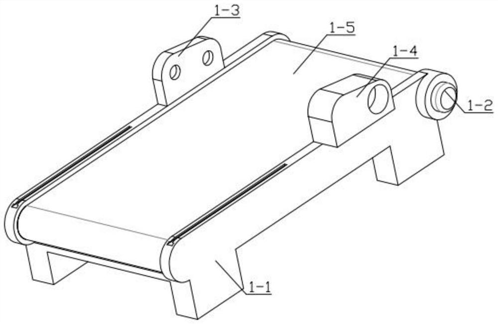
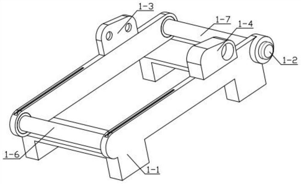
[0039] Combine below Figure 1-15 Describe this embodiment. This embodiment will further explain Embodiment 1. The conveyor belt mechanism 1 includes a base 1-1, a transmission motor 1-2, a side plate 1-3, a side plate 2 1-4, and a conveyor belt 1- 5. The auxiliary transmission shaft 1-6, the main transmission shaft 1-7, the auxiliary transmission shaft 1-6 is installed in the groove provided on the base 1-1, and the conveyor belt 1-5 is installed on the auxiliary transmission shaft 1-6 and the main transmission shaft. On the transmission shaft 1-7, the side plate 1-3 is fixedly installed on the base 1-1, the side plate 2 1-4 is fixedly installed on the base 1-1, and the transmission motor is fixedly installed in the through hole of the base 1-1 1-2, the output end of the transmission motor 1-2 is fixedly installed with the main transmission shaft 1-7, and the other end of the main transmission shaft 1-7 is rotatably installed in the groove provided on the base 1-1.
specific Embodiment approach 3
[0041] Combine below Figure 1-15 Describe this embodiment mode. This embodiment mode will further explain Embodiment 2. The secondary extrusion mechanism 2 includes a driving motor 2-1, a main sprocket 2-2, a driving chain 2-3, and a secondary sprocket 2- 4. The second extrusion shaft 2-5, the first extrusion shaft 2-6, the drive motor 2-1 is fixedly installed in the groove provided on the side plate 2 1-4, and the output end of the drive motor 2-1 is fixed The main sprocket 2-2 is installed, and the main sprocket 2-2 is fixedly installed on one end of the second extruding shaft 2-5, and the other end of the second extruding shaft 2-5 is rotatably installed on the side plate 1-3 In the groove provided, the main sprocket 2-2 is meshed with the drive chain 2-3, and the drive chain 2-3 is meshed with the secondary sprocket 2-4, and the secondary sprocket 2-4 is rotatably installed on the side plate two 1- 4, the auxiliary sprocket 2-4 is fixedly installed on one end of the firs...
PUM
 Abstract
Description
Claims
Application Information
 - Generate Ideas
- Intellectual Property
- Life Sciences
- Materials
- Tech Scout
- Unparalleled Data Quality
- Higher Quality Content
- 60% Fewer Hallucinations
Browse by: Latest US Patents, China's latest patents, Technical Efficacy Thesaurus, Application Domain, Technology Topic, Popular Technical Reports.
© 2025 PatSnap. All rights reserved.Legal|Privacy policy|Modern Slavery Act Transparency Statement|Sitemap|About US| Contact US: help@patsnap.com


