
Acoustic system

A sound system and sound technology, applied in instruments, space heating and ventilation details, household heating and other directions, can solve problems such as difficult to change the relative relationship, reduce sound, equipment impact, etc., to eliminate wind noise, reduce pipe weight, The effect of eliminating fan noise

Pending Publication Date: 2021-05-28
FUJIFILM CORP
View PDF2 Cites 0 Cited by
  • Summary
  • Abstract
  • Description
  • Claims
  • Application Information

AI Technical Summary

Problems solved by technology

[0004] Therefore, it is also possible to use ordinary porous sound-absorbing bodies in the pipe, but this only reduces the sound as a whole, and it is difficult to change the relative relationship that the noise is loud only at the above-mentioned specific frequencies
The ease of hearing prominent specific frequency sounds is well known in the field of psychoacoustics, and there is a need for a method of strongly attenuating only specific sounds, but this is difficult in ordinary porous sound absorbers
[0005] Also, when the porous sound-absorbing body is made of fibrous sound-absorbing body or deteriorated material, its fibers or detached fragments are carried by the wind of the fan and become dust flying, which affects the equipment or is released into the environment, so it is not preferable.

Method used


Image

  • Acoustic system
  • Acoustic system
  • Acoustic system

Examples


Embodiment 1

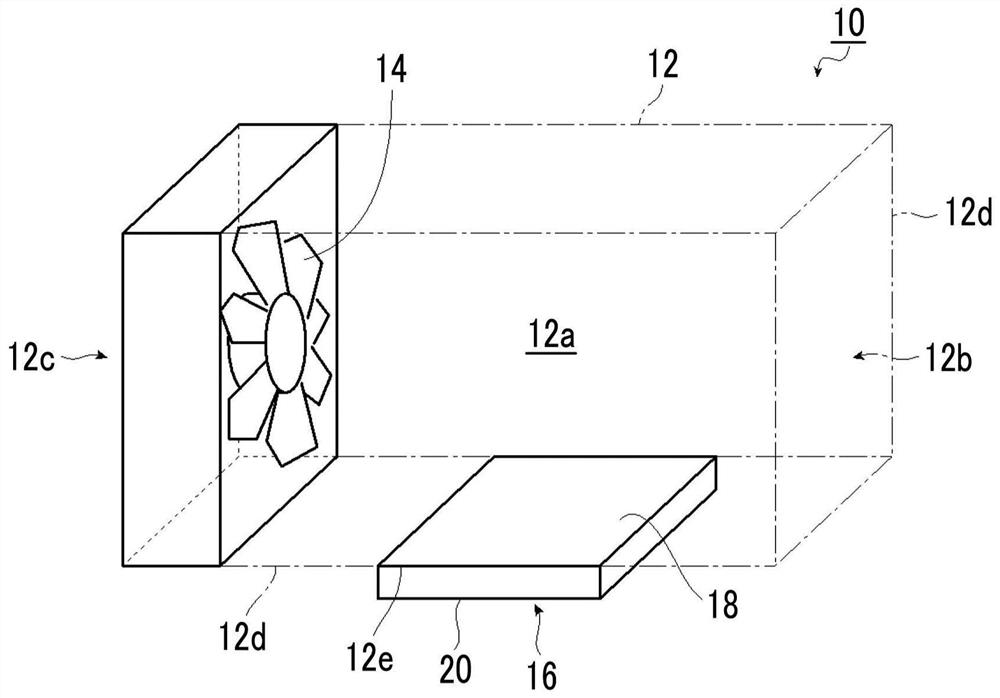
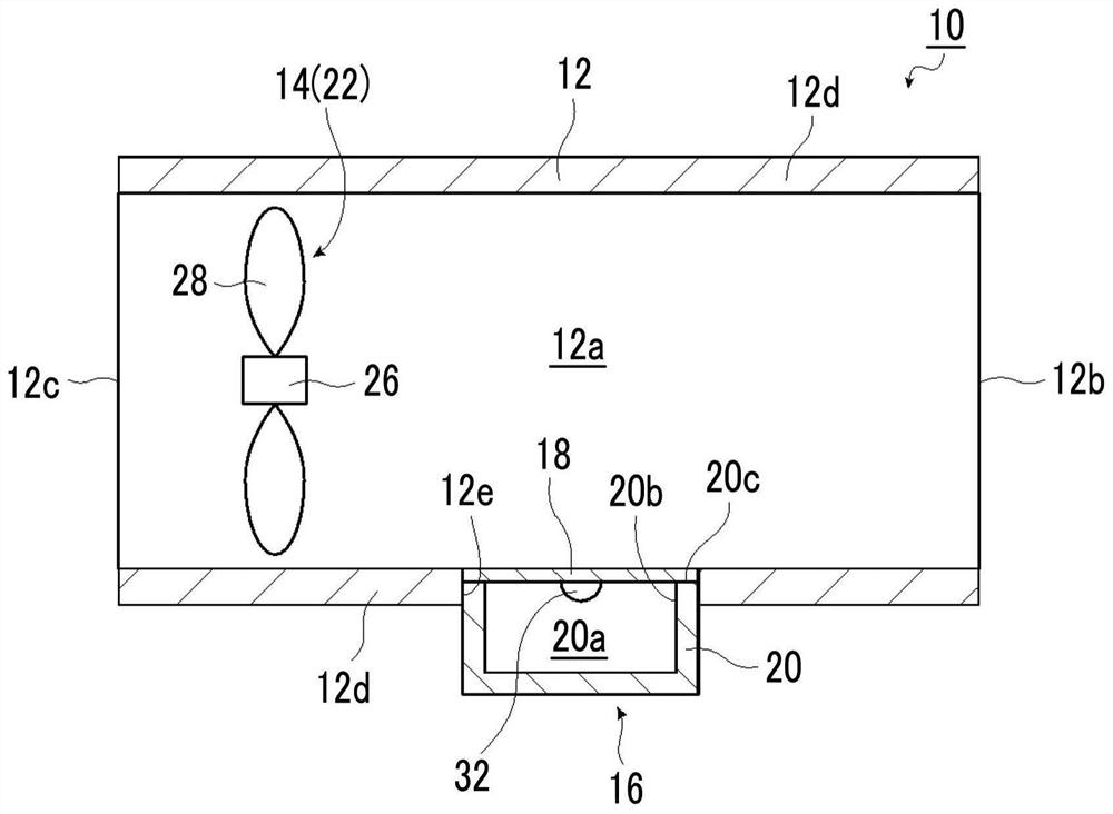
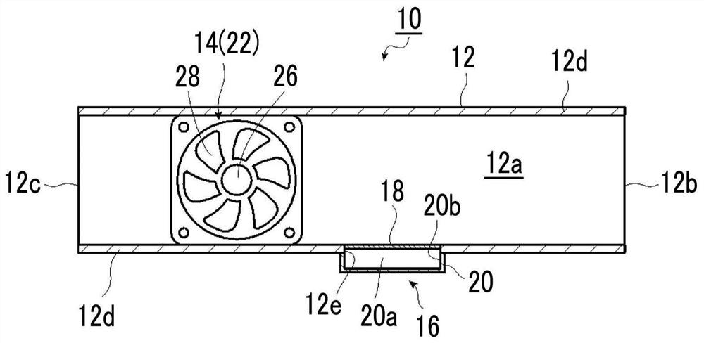
[0273] First, if Figure 37 and Figure 38 As shown, a through hole 12a having a square section of 60mm x 60mm has an overall dimension of 80mm x 80mm including a wall 12d with a thickness of 10mm, and the upper surface of one side end surface of the pipe 12 with a length of 145mm and two on the side, fitted separately Figure 38 The film-type resonator 16 of width 30mm × length 60mm × width 10mm is shown, thus constitutes Figure 37 The end face of one side of the pipe 12 is configured in cross-section. Next, a fan 14 having a square shape of 60 mm x 60 mm and a thickness of 28 mm is attached to one end surface of the duct 12 constructed in this way, and the fan 14 is configured to cover the through hole 12 a of the duct 12 to form the acoustic unit 10 .

[0274] Installed on the suction side of the fan 14 is a duct 13 having through holes 13a of the same size and lined with a polyurethane rubber 13b having a thickness of 10mm and having a cross-sectional dimension of 200m...

Embodiment 2

[0286]

[0287] It is the same measurement system as in Example 1, and the microphone 38 is arranged at a position at a distance of 100 mm at right angles from a position at a downstream side of 100 mm, instead of at a position at a position at a distance of at right angles of 140 mm from a position at a position at a downstream side of 200 mm.

[0288] The amount of current was adjusted so that the dominant sound of the fan 14 became 1500 Hz. At this time, the end wind speed measured by the flow meter was 7.8 m / s. The assay system was carried out with Figure 41A and Figure 41B The comparison of the acoustic unit 10a of Example 2 with the film resonator 16 shown, and the measurement system and Figure 42A and Figure 42B A comparison of the acoustic unit 50 of Comparative Example 1 including the Helmholtz resonator 52 shown.

[0289] As the film-type resonator 16 of the acoustic unit 10a of Embodiment 2, it is set as the following structure: on one surface in the secti...

Embodiment 3、 Embodiment 4

[0302] An experiment was carried out by arranging two rows (Example 3) and four rows (Example 4) of film-type resonators 16 instead of one row in the direction of the channel flow path in the same measurement system as in Example 2. , so as to obtain a greater noise reduction effect experiment. Figure 44 A schematic diagram of a configuration with 4 columns is shown in . show their results in Figure 45 .

[0303] Figure 45 The spectrum of the sound volume at the microphone position measured under the arrangement conditions of each film-type resonator 16 is shown in . Also, Table 1 shows a comparison of peak sound volumes, including the results of Example 2. It has been found that a greater noise reduction effect can be obtained by arranging a plurality of rows of film resonators 16 in the flow path direction of the pipe. When arranged in 4 rows, the noise reduction effect of more than 15dB can be obtained.

[0304] In addition, in Example 2, Example 3, and Example 4, ...


PUM


Abstract

This acoustic system comprises a cylindrical duct that allows a fluid to flow therethrough, an internal sound source arranged inside the upstream side of the duct or on an outer peripheral part of the duct that communicates with the inside of the upstream side of the duct or an external sound source located outside an end of the duct, and a film-like material that is formed as a part of the wall of the duct and vibrates in response to sound. The acoustic system creates an acoustic resonance through a structure including the film-like material and a closed space behind the film-like material so that sound propagating through the duct from a sound source and exiting from the end of the duct at the downstream side thereof is minimized, and the external sound source is located outside the end of the duct at a distance less than the wavelength of the acoustic resonance frequency from the end of the duct. By arranging a compact membrane-type resonance structure in a direction parallel to a flow passage in this acoustic system, wind will not directly hit the film surface perpendicularly thereto, and wind noise can be eliminated because there is no through-hole or aperture.

Description

technical field [0001] The present invention relates to an acoustic system including: a structure for flowing a fluid containing wind and / or heat; and a duct attached to the structure, such as a blower such as a fan. In particular, the present invention relates to an acoustic system that effectively dampens the noise of a specific frequency generated by a fan within a duct. Background technique [0002] For a long time, in buildings and houses, etc., ventilation ducts such as air-conditioning ducts equipped with fans are widely used for indoor air conditioning, ventilation and / or air supply, and due to the requirements for comfort and quietness in the house, Noise reduction and miniaturization are strongly desired. [0003] Specifically, noise that stands out at a specific frequency determined by the number and rotational speed of fan blades has become a big problem with fan noise. [0004] Therefore, it is also possible to use an ordinary porous sound-absorbing body in th...

Claims


Application Information

Patent Timeline
Patent Type & Authority Applications(China)
IPC IPC(8): G10K11/172G10K11/16
CPCG10K11/172F24F13/24F24F2013/247G10K11/161
Inventor 白田真也菅原美博大津晓彦山添昇吾
Owner FUJIFILM CORP
Learn More