Eureka AIR delivers breakthrough ideas for toughest innovation challenges, trusted by R&D personnel around the world.

Form relieved tooth radiator and manufacturing process thereof

A technology for radiators and shoveling teeth, which is applied in the field of shoveling tooth radiators and its manufacturing process, which can solve the problem of the difficulty in balancing the space occupied by the radiator with the heat dissipation efficiency, the inability to meet the needs of the miniaturization of home appliances, and the increase in the operating power of power devices, etc. problems, to achieve the effect of convenient maintenance and replacement, simple structure, and improved assembly efficiency

Pending Publication Date: 2021-05-28
镇江宏联电工有限公司
View PDF0 Cites 3 Cited by
  • Summary
  • Abstract
  • Description
  • Claims
  • Application Information

AI Technical Summary

Problems solved by technology

[0002] With the improvement of people's requirements for the quality of life, household appliances have gradually developed into a trend of small size and high efficiency. This leads to the increase of the operating power of power devices and the increase of heat dissipation requirements for volume density when the original space volume is limited. , it is difficult to take into account the space occupied by traditional radiators and the heat dissipation efficiency, which cannot meet the needs of the miniaturization of home appliances

Method used


Image

  • Form relieved tooth radiator and manufacturing process thereof
  • Form relieved tooth radiator and manufacturing process thereof
  • Form relieved tooth radiator and manufacturing process thereof

Examples


Embodiment Construction

[0028]In order to deepen the understanding of the present invention, the present invention will be further detailed in connection with the embodiments and the accompanying drawings, which is not intended to be construed as limiting the scope of the invention.

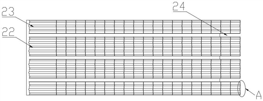
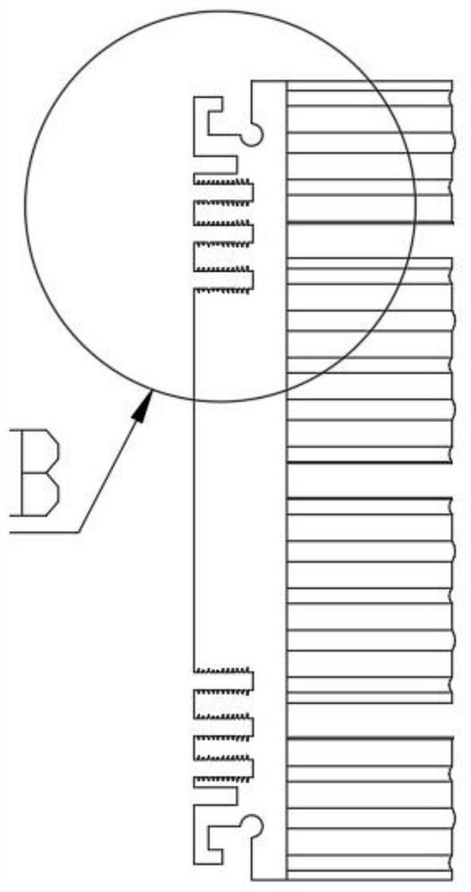
[0029]Such asFigure 1-8As shown, a shovel and a heat dissipator comprising a mounting portion 10 and a heat dissipation portion 20, the heat dissipation portion 20 is located on the upper surface of the mounting portion 10, and the heat dissipation portion 20 comprises a ripple arm 21 provided with a plurality of arrays, the corrugation There is an α angle between the shovel teeth 21 and the mounting portion 10, the surface of the strip arm is wavy; the bellows 21 includes two columns of wide rippled shovel teeth 22 and two narrow corrugated shovel teeth groups 23; The narrow-striped shovel teeth 23 are located on both sides of the wide ripple shovel teeth group 22; the adjacent columns are provided with a spacing air groove 24....


PUM


Abstract

The invention discloses a form relieved tooth radiator and a manufacturing process thereof, the form relieved tooth radiator comprises a mounting part and a radiating part, the radiating part is located on the upper surface of the mounting part, the radiating part comprises a plurality of corrugated form relieved teeth arranged in an array, a certain angle is formed between the corrugated form relieved teeth and the mounting part, and the surfaces of the corrugated form relieved teeth are wavy; and clamping grooves are formed in the two sides of the mounting part, and a plurality of groups of mounting grooves are formed in the lower surface of the mounting part. The form relieved tooth radiator is simple in structure and convenient to machine, the product base material can be produced in batches at low cost only through extrusion forming of a profile mold, and the corrugated relieved teeth of the radiating part can be produced into corrugated relieved teeth with different angles and different heights only through corrugated relieved tooth cutters with different angles so as to meet household appliances with various sizes and radiating requirements. The heat dissipation area of the heat dissipation part can be greatly increased through the corrugated form relieved teeth arranged at the inclined angle and the wavy lines on the surfaces of the corrugated form relieved teeth. The structure is simple, and the reserved mounting grooves and clamping grooves can be quickly assembled and disassembled.

Description

Technical field[0001]The present invention relates to the field of heat sink, and more particularly to a shovel teeth radiator and a manufacturing process thereof.Background technique[0002]As people improve their quality requirements, home appliance products have gradually evolved into a small size, and the efficiency is high, so that in the case of the original spatial volume, the operating power of the power device is increased, and the heat dissipation of the volume density is improved. The traditional radiator occupies the space and heat dissipation efficiency, and it is impossible to meet the needs of miniaturization of home appliances.Inventive content[0003]It is an object of the present invention to solve the deficiencies of the above prior art, proposed a shovel and a heat dissipation portion, the heat dissipation portion, where the heat dissipation portion is provided, including a variety of array settings Shot, the corrugated shovel teeth and the mounting portion have a ce...

Claims


Application Information

Patent Timeline
Patent Type & Authority Applications(China)
IPC IPC(8): H05K7/20
CPCH05K7/2039
Inventor 杨田
Owner 镇江宏联电工有限公司
Why Eureka
Eureka Blog
Learn More