Non-contact magnetic sensor

A magnetic sensor, non-contact technology, applied in the field of sensors, can solve the problems of unable to adjust the pressure range of the sensor, inconvenient for fixed installation, unable to directly read the pressure value, etc.

Active Publication Date: 2021-05-28
三桥惠(佛山)新材料有限公司 +1
View PDF7 Cites 0 Cited by
  • Summary
  • Abstract
  • Description
  • Claims
  • Application Information

AI Technical Summary

Problems solved by technology

However, there are some problems with the sensor at present: 1. When the sensor is in use, it is not convenient for fixed installation; 2. When the sensor is in use, the pressure range controlled by the sensor cannot be adjusted, and the internal pressure value cannot be directly read

Method used


Image

  • Non-contact magnetic sensor
  • Non-contact magnetic sensor
  • Non-contact magnetic sensor

Examples


Embodiment

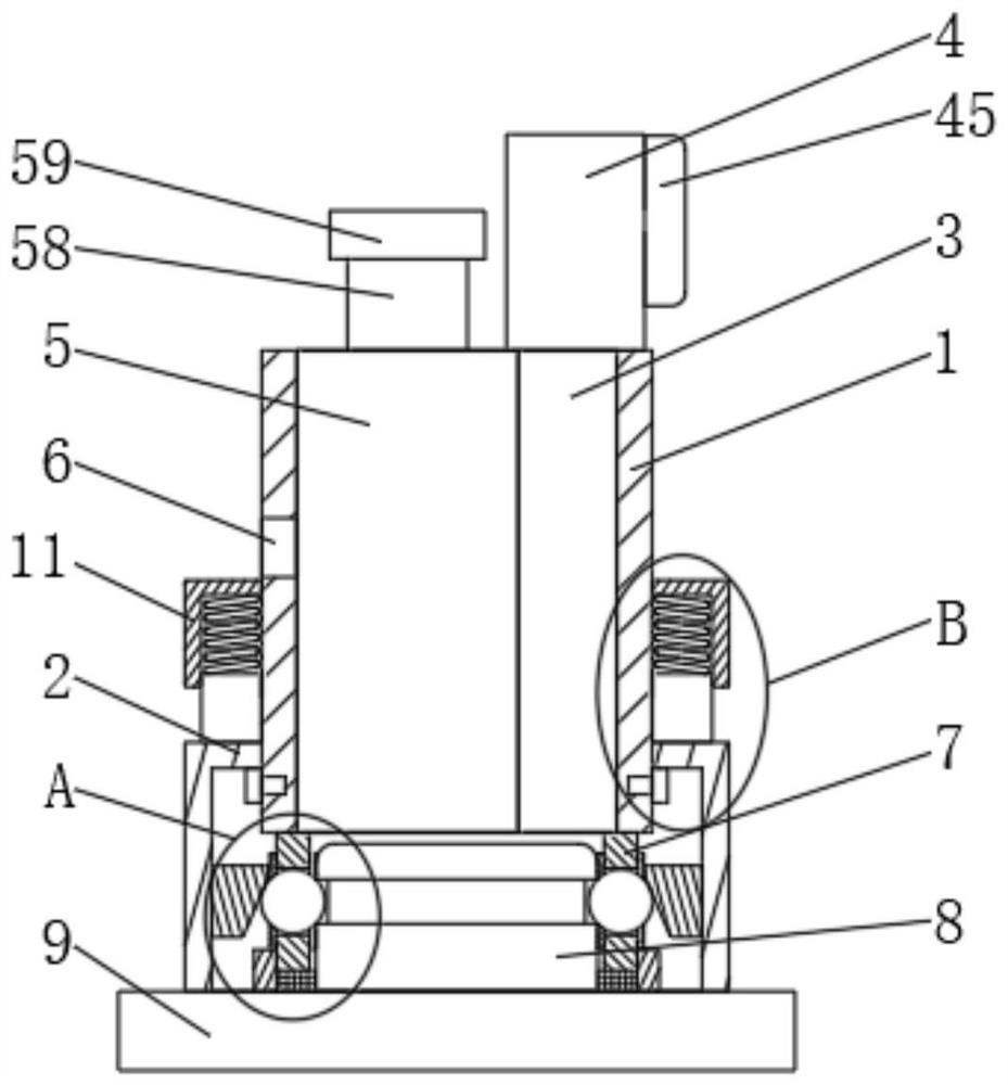
[0026] A non-contact magnetic sensor, including a housing 1, a sliding ring 2, a pressure gauge 3, a pressure box 4, an inductor 5, a vent hole 6, a connection port 7, a fixed port 8, a base 9, a slider 10 and Drive shaft 42, the outer side of the housing 1 is slidably connected with a sliding ring 2, the inner wall of the housing 1 is fixedly connected with a pressure gauge 3, and the upper end of the pressure gauge 3 is fixedly connected with a pressure tank 4, the housing An inductor 5 is fixedly connected to the inner wall of the body 1, and the right end of the inductor 5 is fixedly connected to the left end of the pressure gauge 3. The housing 1 is provided with a vent hole 6, and the housing 1 The lower end is fixedly connected with a connecting port 7, the inside of the connecting port 7 is clamped with a fixed port 8, the lower end of the fixed port 8 is fixedly connected with a base 9, and the lower end of the sliding ring 2 is in contact with the upper end of the bas...


PUM


Abstract

The invention discloses a non-contact magnetic sensor, and the magnetic sensor comprises a shell, a sliding ring, a pressure meter, a pressure box, an inductor, a first exhaust hole, a connecting port, a fixing port, a base, a sliding block and a driving shaft; the outer side of the shell is slidably connected with the sliding ring, the inner wall of the shell is fixedly connected with the pressure meter, the upper end of the pressure meter is fixedly connected with the pressure box, an inductor is fixedly connected to the inner wall of the shell, the right end of the inductor is fixedly connected with the left end of the pressure gauge, a first exhaust hole is formed in the shell, a connecting port is fixedly connected to the lower end of the shell, a fixing port is clamped in the connecting port, and a base is fixedly connected to the lower end of the fixing port; the lower end of the sliding ring is in contact connection with the upper end of the base, and the interior of the shell is connected with a screw through threads. The invention relates to a non-contact magnetic sensor which has the advantages of being convenient to install and capable of adjusting the pressure sensing range.

Description

technical field [0001] The invention belongs to the technical field of sensors, in particular to a non-contact magnetic sensor. Background technique [0002] A sensor is a detection device that can sense the measured information and convert the sensed information into electrical signals or other required forms of information output according to certain rules to meet the requirements of information transmission, processing, storage, and display. , recording and control requirements. The characteristics of sensors include: miniaturization, digitization, intelligence, multi-function, systemization, and networking. It is the first link to realize automatic detection and automatic control. However, there are some problems with the sensor at present: 1. When the sensor is in use, it is not convenient for fixed installation; 2. When the sensor is in use, the pressure range controlled by the sensor cannot be adjusted, and the internal pressure value cannot be directly read. There...

Claims


Application Information

Patent Timeline
Patent Type & Authority Applications(China)
IPC IPC(8): G01L9/00G05D16/20
CPCG01L9/0091G05D16/2006
Inventor 黄玮森胡锦文其他发明人请求不公开姓名
Owner 三桥惠(佛山)新材料有限公司
Why Eureka
Try Eureka