Oil sealing cover structure with thrust function

A technology of oil seal and function, applied in the field of oil seal structure, can solve the problem of low negative pressure resistance of the shaft system, achieve high installation accuracy, improve reliability, and simple structure

Pending Publication Date: 2021-05-28
HUNAN TYEN MACHINERY
View PDF0 Cites 0 Cited by
  • Summary
  • Abstract
  • Description
  • Claims
  • Application Information

AI Technical Summary

Problems solved by technology

[0004] The technical problem to be solved by the present invention is to overcome the defects of the prior art, provide an oil sealing cover structure with a thrust function, and solve the current problem of low negative pressure resistance of the shaft system

Method used


Image

  • Oil sealing cover structure with thrust function
  • Oil sealing cover structure with thrust function
  • Oil sealing cover structure with thrust function

Examples


Embodiment Construction

[0016] The preferred embodiments of the present invention will be described below in conjunction with the accompanying drawings. It should be understood that the preferred embodiments described here are only used to illustrate and explain the present invention, and are not intended to limit the present invention.

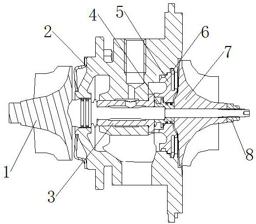
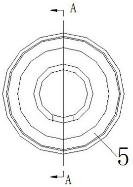
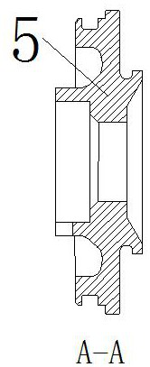
[0017] like Figure 1-Figure 4 As shown, an oil seal cover structure with a thrust effect includes a turbine rotor 1, a bearing body 2, an integral bearing sleeve 3 and an impeller 7, the integral bearing sleeve 3 is installed inside the bearing body 2, and the turbine The rotor 1 is installed in the inner hole of the integral bearing sleeve 3, the left and right ends of the turbine rotor 1 extend out of the bearing body 2, the impeller 7 is installed on the right side outside the turbine rotor 1, and the turbine rotor 1 is located outside the impeller A sealing sleeve 4 is installed between 7 and the integral bearing sleeve 3, and an oil sealing cover 5 is installe...


PUM


Abstract

The invention discloses an oil sealing cover structure with a thrust function, and particularly relates to the technical field of turbochargers. The oil sealing cover structure comprises a turbine rotor, a bearing body, an integral bearing sleeve and an impeller, the integral bearing sleeve is installed inside the bearing body, the turbine rotor is installed in an inner hole of the integral bearing sleeve, the left end and the right end of the turbine rotor extend out of the bearing body, the impeller is installed on the right side outside the turbine rotor, and a sealing sleeve is installed outside the turbine rotor and located between the impeller and the integral bearing sleeve. The oil sealing cover structure with the thrust function is simple in structure, convenient to install and high in installation precision, a thrust pressing plate is omitted in the structure, thrust can be achieved through an oil sealing cover, cost is effectively reduced, meanwhile, the volume of a lubricating oil cavity of the bearing body is increased, the negative pressure resistance of a shaft system can be improved, the reliability of a supercharger is improved, and the problem that an existing shaft system is low in negative pressure resistance is solved.

Description

technical field [0001] The invention relates to the technical field of turbochargers, in particular to an oil sealing cap structure with a thrust function. Background technique [0002] The turbocharger uses the energy of the combustion exhaust gas to drive the compressor to rotate, and the compressor compresses the air to increase the intake air density, thereby improving the combustion efficiency of the internal combustion engine and achieving more work output. During the working process of the turbocharger, it is simultaneously subjected to the axial thrust of the gas from the compressor end and the turbine end. The axial force changes with the change of the engine operating conditions. Therefore, the turbocharger shafting must be designed with an axial thrust structure to withstand axial force. [0003] The current thrust structure of the shaft system is that the integral bearing sleeve is installed on the shaft of the turbine rotor. The two ends of the integral bearing...

Claims


Application Information

Patent Timeline
Patent Type & Authority Applications(China)
IPC IPC(8): F04D29/05F04D29/10F04D29/26F04D29/063
CPCF04D29/05F04D29/063F04D29/102F04D29/266F05D2220/40
Inventor 张华然曹刚张涛李琳李锋刘朝晖潘航宇杨迪
Owner HUNAN TYEN MACHINERY
Why Eureka
Try Eureka