
Image display method, vehicle-mounted display system and vehicle

A vehicle-mounted display and image technology, applied in the automotive field, can solve problems such as inconsistencies in images, large visual differences, and low authenticity of video images

Active Publication Date: 2021-05-28
VARITRONIX HEYUAN DISPLAY TECH
View PDF4 Cites 2 Cited by
  • Summary
  • Abstract
  • Description
  • Claims
  • Application Information

AI Technical Summary

Problems solved by technology

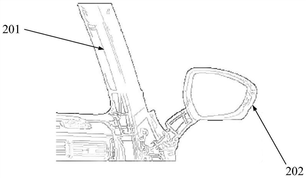
[0003] The existence of the A-pillar blind spot is one of the important causes of traffic accidents. The inconvenience of sight blocking is more obvious especially when the driver is turning or changing lanes. Therefore, we hope that the narrower the A-pillar, the better, and the A-pillar supports the car. The front part requires a certain degree of rigidity, and it is difficult for existing vehicles to meet the driving observation requirements and ensure a certain safety factor.
[0004] At present, the video images presented by other electronically transparent A-pillars are not very realistic. Because the optical parameters of the human eye and the camera are different, and the angle of view of the human eye is inconsistent with the field of view of the camera, the images collected by the direct display camera must follow those without the A-pillar. In some cases, the images seen by human eyes are inconsistent, resulting in large visual differences

Method used


Image

  • Image display method, vehicle-mounted display system and vehicle
  • Image display method, vehicle-mounted display system and vehicle
  • Image display method, vehicle-mounted display system and vehicle

Examples


Embodiment Construction

[0028] In order to make the purpose, technical solution and advantages of the present application clearer, the present application will be further described in detail below in conjunction with the accompanying drawings and embodiments. It should be understood that the specific embodiments described here are only used to explain the present application, and are not intended to limit the present application.

[0029] Hereinafter, the terms "first", "second" and other ordinal numerals in this application are only used for descriptive purposes, and should not be understood as indicating or implying relative importance or implicitly indicating the quantity of indicated technical features. Thus, a feature defined as "first" and "second" may explicitly or implicitly include one or more of these features. In the description of the embodiments of the present application, unless otherwise specified, "plurality" means two or more.

[0030] It should be understood that when used in this ...


PUM


Abstract

The invention provides an image display method which is applied to a vehicle-mounted system, the vehicle-mounted system comprises a camera and a flexible display screen, the flexible display screen is installed on a column A. The display method comprises the steps of obtaining a blind area image corresponding to the column A, wherein the blind area image is a blind area image corresponding to the column A when a driver sees the column A, and an image which is blocked by the A column and is not seen by the driver is intercepted from the image shot by the camera; performing view angle conversion on the blind area image to obtain a target image; and displaying the target image on a flexible display screen. According to the method, the driving image is obtained through the single camera installed on the single side outside the vehicle, then the blind area image is intercepted from the image, the blind area image is subjected to view angle conversion to obtain the picture, connected with the image seen by a driver, on the display screen on the single side, and the method is low in cost, simple in structure and convenient to implement; the visual difference is better eliminated, so that the transparency of the A column is realized.

Description

technical field [0001] The present application relates to the technical field of automotive electronics, in particular to an image display method, a vehicle display system and an automobile. Background technique [0002] The A-pillar, the English name is A-pillar, is the connecting column connecting the roof and the front cabin between the left and right front of the vehicle, between the engine compartment and the cockpit, above the left and right rearview mirrors. Since the A-pillar is between the engine compartment and the cockpit and above the left and right rearview mirrors, it will block part of the driver's turning vision. The blind area of ​​vision formed by the A-pillar blocking the driver's vision during driving is called the A-pillar blind area. . [0003] The existence of the A-pillar blind spot is one of the important causes of traffic accidents. The inconvenience of sight blocking is more obvious especially when the driver is turning or changing lanes. Therefor...

Claims


Application Information

Patent Timeline
IPC IPC(8): B60W50/14B60W40/08H04N7/18
CPCB60W50/14B60W40/08H04N7/18B60W2050/146
Inventor 金浩阳宋松韩永刚
Owner VARITRONIX HEYUAN DISPLAY TECH
Learn More