
Automatic indexing control method and device for fully-automatically-exchanged multidirectional swing head

An automatic indexing and control method technology, applied in the field of CNC machine tools, can solve the problems of tooth gap change, top teeth, and the inability to independently correct the angular gap gap change, etc., and achieve the effect of precise tooth gap compensation value

Active Publication Date: 2021-05-28
NINGBO SKY MASTER PRECISION MASCH CO LTD
View PDF6 Cites 0 Cited by
  • Summary
  • Abstract
  • Description
  • Claims
  • Application Information

AI Technical Summary

Problems solved by technology

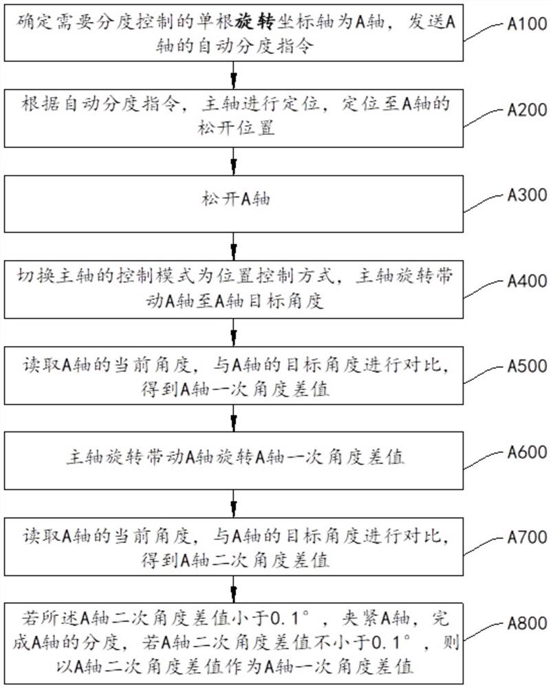
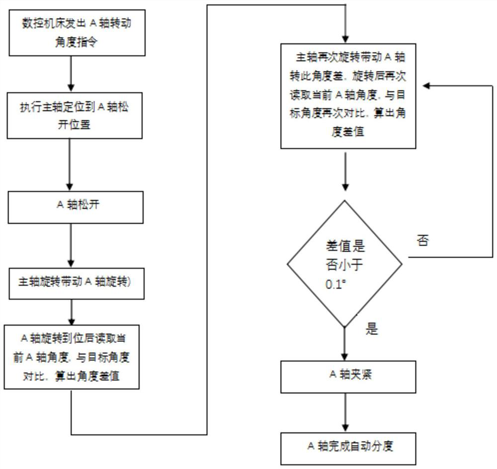
[0007] The present invention aims at the above-mentioned defects existing in the prior art, and proposes an automatic indexing control method and device for a fully automatic exchange multi-directional swing head. For the problem of backlash change, the present invention solves the gap difference between the A-axis and the C-axis by separately correcting the backlash of the A-axis and the C-axis, so that the compensation value of the backlash is more accurate
By driving the C-axis to swing left and right once until the upper and lower teeth of C are clamped, the problem of the top teeth of the C-axis caused by the change of the tooth gap caused by heat is solved.

Method used


Image

  • Automatic indexing control method and device for fully-automatically-exchanged multidirectional swing head
  • Automatic indexing control method and device for fully-automatically-exchanged multidirectional swing head
  • Automatic indexing control method and device for fully-automatically-exchanged multidirectional swing head

Examples


Embodiment 1

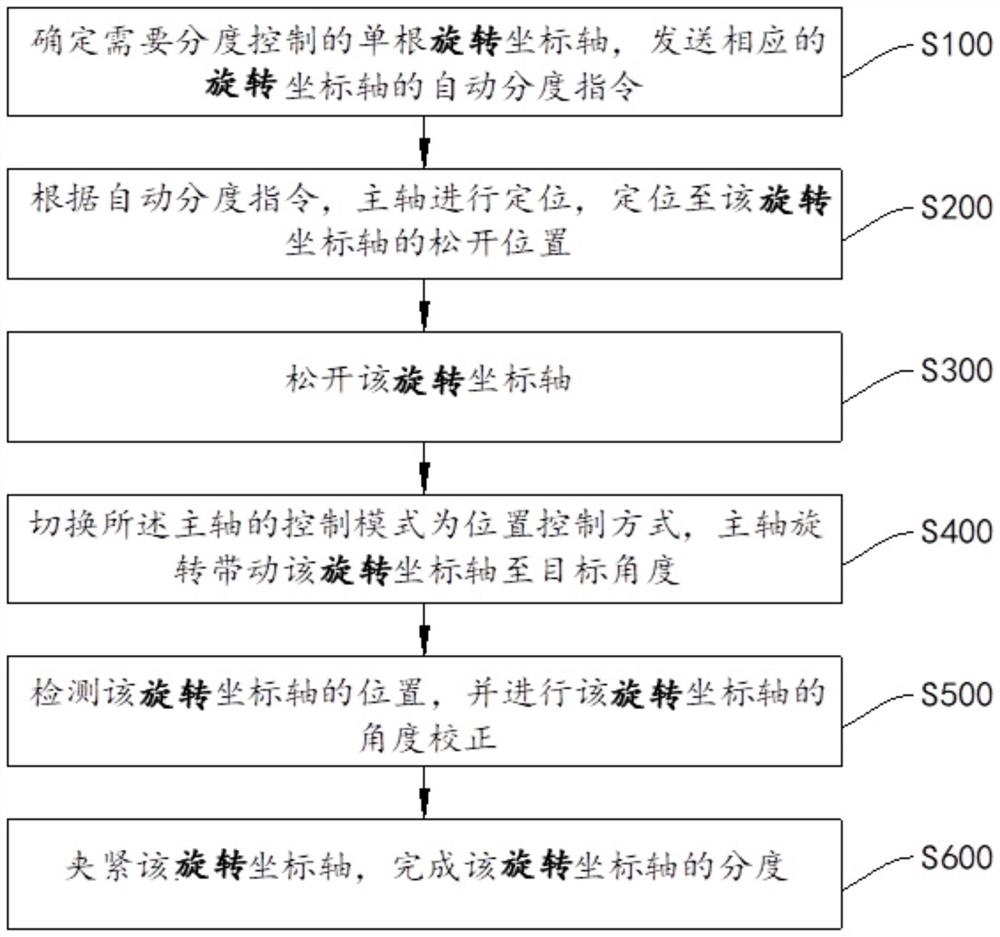
[0083] see figure 1 , the automatic indexing control method comprises the following steps:

[0084] S100) Determine the single rotating coordinate axis that needs indexing control, and send the corresponding automatic indexing command of the rotating coordinate axis. In this embodiment, the rotating coordinate axis is the A axis and the C axis, and at the same time in the automatic indexing control method One rotating coordinate axis is indexed in a single time, that is, the tooth gap of the A axis and the tooth gap of the C axis are separately corrected.

[0085] S200) According to the automatic indexing command, the spindle is positioned to the release position of the rotating coordinate axis. For the A axis and the C axis, the release points of the two axes are different and need to be calculated separately.

[0086] S300) Loosen the rotating coordinate axis through a hydraulic device.

[0087] S400) Switch the control mode of the spindle to the position control mode (the...


PUM


Abstract

The invention relates to the field of numerically-controlled machine tools, and specifically relates to an automatic indexing control method and device for a fully-automatically-exchanged multidirectional swing head. The automatic indexing control method for the fully-automatically-exchanged multidirectional swing head comprises the following steps: determining a single rotating coordinate axis needing indexing control, and sending an automatic indexing instruction for the corresponding rotating coordinate axis; locating a main axis to a loosening position for the rotating coordinate axis according to the automatic indexing instruction; loosening the rotating coordinate axis; switching a control mode for the main axis into a position control mode, and enabling the main axis to rotate to drive the rotating coordinate axis to a target angle; detecting the position of the rotating coordinate axis, and carrying out angle correction for the rotating coordinate axis; and clamping the rotating coordinate axis, and completing indexing for the rotating coordinate axis. According to the invention, gap difference between an A axis and a C axis is solved by separately compensating and correcting a tooth gap of the A axis and a tooth gap of the C axis, so that a tooth gap compensation value is more accurate. The C axis is driven to swing left and right once until upper teeth and lower teeth of the C axis are clamped, so that the problem of tooth jacking of the C axis due to tooth gap change caused by heating is solved.

Description

technical field [0001] The invention relates to the field of numerical control machine tools, in particular to a method and device for automatic indexing control of a fully automatic exchange multi-directional swing head. Background technique [0002] In CNC machine tools, the three linear coordinate axes are generally called X, Y, and Z axes, and the rotation axes that rotate around these three axes are called A, B, and C axes, and the C axis is the movement that rotates around the Z axis. axis. C-axis control refers to treating the C-axis as a servo axis, called spindle contour control, which can participate in the interpolation control of other coordinates. If the spindle motor is used to control the C axis, it is called the Cs axis. In this case, the rotation position (rotation angle) of the spindle in the lathe system is not controlled by the feed servo motor, but is realized by the spindle motor of FANUC Corporation of Japan. The position of the spindle (Angle) is de...

Claims


Application Information

Patent Timeline
Patent Type & Authority Applications(China)
IPC IPC(8): B23Q16/06B23Q15/26
CPCB23Q16/06B23Q15/26
Inventor 李全林杨达赵建夫徐文强赵敏朱炜炜陈定钧袁鹏冲石海方俞杲杰孙殿承宋乐求孙吕挺叶科剑
Owner NINGBO SKY MASTER PRECISION MASCH CO LTD
Learn More