
A water treatment automatic pulse air lift sludge removal device

An automatic pulse and water treatment technology, applied in the direction of water/sludge/sewage treatment, flocculation/sedimentation water/sewage treatment, special treatment goals, etc., to reduce over-flow resistance loss, improve air lift and sludge discharge efficiency, and realize instantaneous Effect of Pulse Gas Throughput

Active Publication Date: 2022-06-24
宜兴市荣盛达环保有限公司
View PDF8 Cites 0 Cited by
  • Summary
  • Abstract
  • Description
  • Claims
  • Application Information

AI Technical Summary

Problems solved by technology

[0009] The purpose of the present invention is to provide a new type of water treatment automatic pulse air lift sludge removal device to overcome some problems existing in the current existing devices, to improve the efficiency of air lift, to expand the scope of application, and to achieve long-term safe operation

Method used


Image

  • A water treatment automatic pulse air lift sludge removal device
  • A water treatment automatic pulse air lift sludge removal device
  • A water treatment automatic pulse air lift sludge removal device

Examples


Embodiment Construction

[0027] The present invention will be described in detail below with reference to the accompanying drawings and specific embodiments.

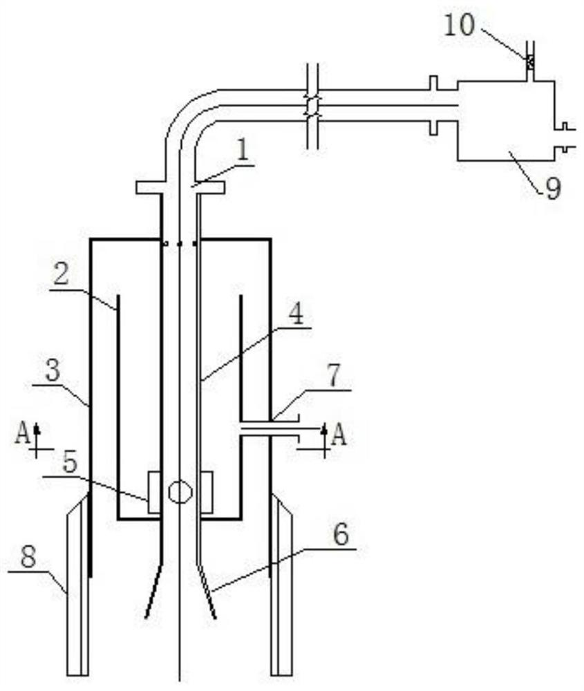
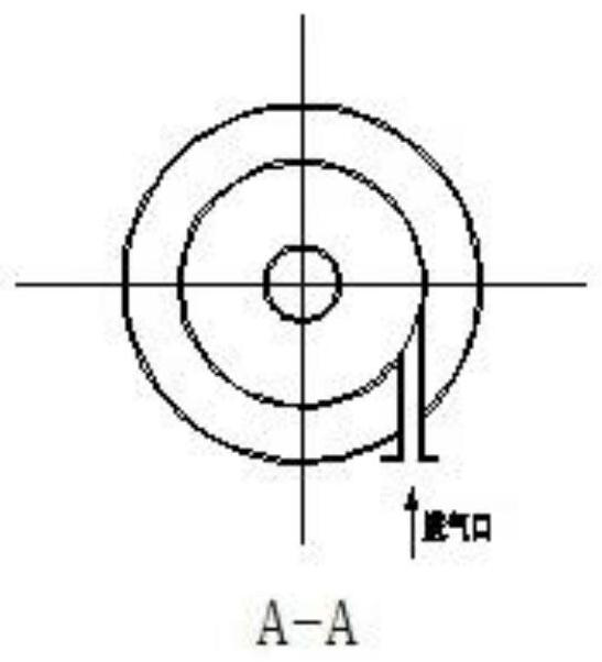
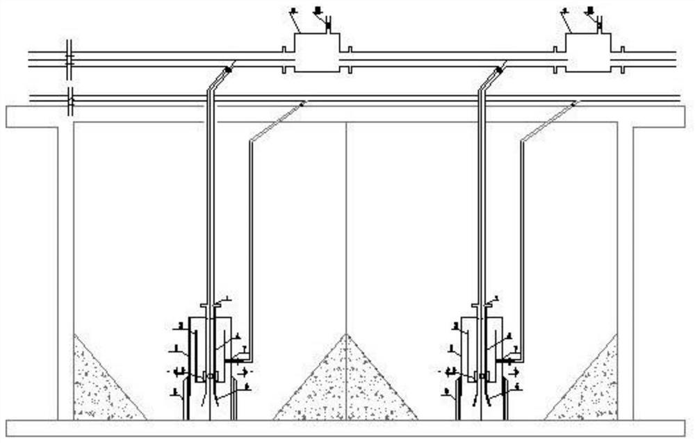
[0028] see Figure 1-2 , an embodiment provided by the present invention: a new type of automatic pulse air lift sludge discharge device, including a gas storage outer cavity 3, a gas storage inner cavity 2, a material inlet 6, a material outlet 1, a pulse tube 4, and a pulse component 5 , an air inlet pipe 7 and a fixing bracket 8, the air storage inner cavity 2 opens upward, the air storage outer cavity 3 opens downward, the air storage outer cavity 3 is inverted and arranged around the air storage inner cavity 2, and the air inlet pipe 7 Passing through the gas storage outer cavity 3 and connected with the air inlet on the gas storage inner cavity 2, the material inlet 6 is located under the gas storage inner cavity 2 and is connected with the lower end of the pulse tube 4, and the material outlet 1 is located in the gas storage cavity 2. T...


PUM


Abstract

The invention discloses a new type of automatic pulse air lifting sludge removal device, which comprises an outer cavity for gas storage, an inner cavity for gas storage, a material inlet, a material outlet, a pulse tube, a pulse component, an air inlet tube and a fixed bracket. The opening of the cavity is upward, the opening of the outer cavity of the gas storage is downward, and the outer cavity of the gas storage is set upside down around the inner cavity of the gas storage. The material inlet is located below the inner cavity of the gas storage and is connected to the lower end of the pulse tube, and the material outlet is located above the outer cavity of the gas storage and is connected to the upper end of the pulse tube. The invention has smooth mud discharge, no blockage, novel structure, no transmission parts, good reliability, energy saving, arbitrary arrangement of mud discharge points, easy operation, permanent use and maintenance-free, and effectively solves gravity / artificial / sludge pump multiple faults The problem. It can ensure the long-term stable operation of the system without maintenance.

Description

technical field [0001] The invention belongs to the field of sludge discharge and sludge de-digestion in a water treatment system, and in particular relates to a novel automatic pulse air-lifting sludge discharge device for water treatment. Background technique [0002] At present, the sedimentation tanks, clarifiers, secondary sedimentation tanks, sludge tanks, oil sludge tanks, biochemical reaction tanks and other sludge discharge methods in industrial and urban water treatment systems mainly use traditional gravity sludge discharge and sewage pump sludge discharge. Especially due to the complex composition and diverse properties of waste liquid and solid-liquid mixture (sand, viscous liquid, toxic fluid, concentrated sludge and solid content, temperature, etc.) The operation and maintenance management, production safety and water treatment cost of the traditional sludge discharge method clarification and separation system will all have a certain impact. [0003] Using gr...

Claims


Application Information

Patent Timeline
Patent Type & Authority Patents(China)
IPC IPC(8): B01D21/24C02F1/52
CPCB01D21/245C02F1/52C02F2303/14
Inventor 王庆芬丁晟颉岳振平侯刘涛
Owner 宜兴市荣盛达环保有限公司
Learn More