Axial sealing structure and washing machine adopting axial sealing structure

An axial sealing and axial technology, applied in the sealing and application of other washing machines, engines, etc., can solve the problems of short life, shaft and water seal wear, accelerated water seal wear, etc.

Pending Publication Date: 2021-05-25
柴睿明
View PDF1 Cites 0 Cited by
  • Summary
  • Abstract
  • Description
  • Claims
  • Application Information

AI Technical Summary

Problems solved by technology

However, the allowable amount of wear in the radial direction of the water seal is relatively small, that is, it will be damaged and fail if the wear exceeds the allowable amount; therefore, its life is not long, which affects the performance and quality of the washing machine
In other industries, there are also cases where the shaft rotates in the shaft hole but the shaft and the shaft hole are soaked in water or even soaked in sewage. The shaft and the shaft hole are also sealed with a water seal, but the sewage will accelerate the wear of the water seal ; After the water corrodes the shaft, it will accelerate the wear of the shaft and water seal

Method used


Image

  • Axial sealing structure and washing machine adopting axial sealing structure
  • Axial sealing structure and washing machine adopting axial sealing structure
  • Axial sealing structure and washing machine adopting axial sealing structure

Examples


Embodiment Construction

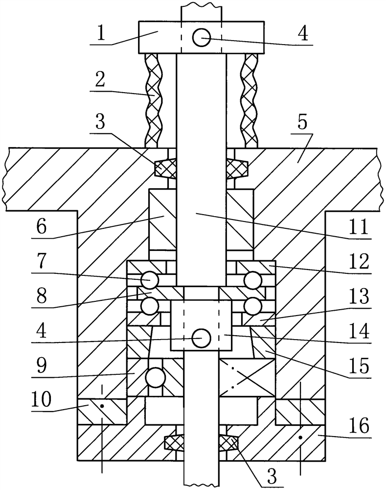
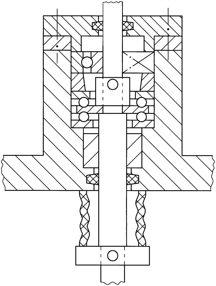
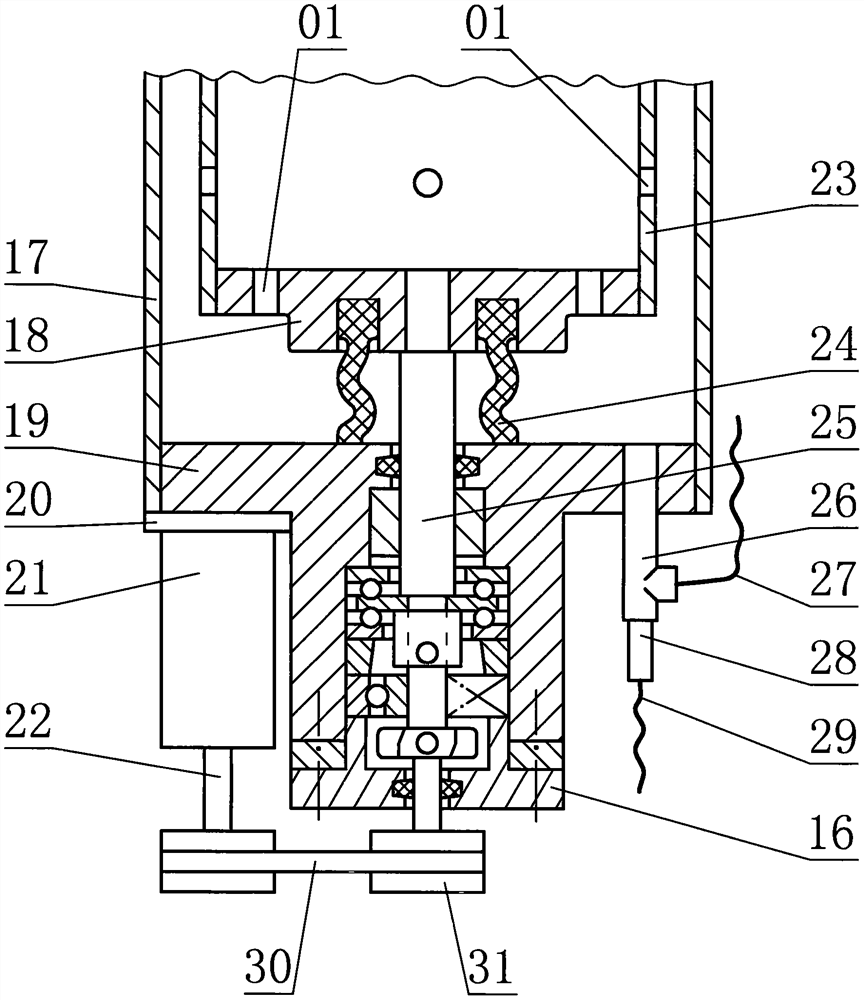
[0040] Combine below Figure 1 to Figure 18 , the present invention is further described:

[0041] figure 1 The shown axial sealing structure includes a support plate and a first type of transmission shaft, the support plate has a shaft hole, and the first type of transmission shaft is installed in the shaft hole of the support plate by a coupling device; the first type of transmission shaft It can be rotated at any angle in the shaft hole of the support plate, and the movement of the first transmission shaft in the other five directions is restricted. The plate is set on the first type of transmission shaft and the relative axial movement between the two is restricted, and the shaft hole of the sealing plate is sealed from the first type of transmission shaft; the sealing plate is located on the support plate Above, the first type of axial seal sleeve is installed between the sealing plate and the support plate, the main body of the first type of axial seal sleeve is tubul...


PUM


Abstract

The invention discloses an axial sealing structure which comprises a supporting plate and a transmission shaft. The supporting plate is provided with a shaft hole, and the transmission shaft is installed in the shaft hole of the supporting plate through a connecting device. The transmission shaft can rotate at any angle in the shaft hole of the supporting plate, and the other five degrees of freedom of the transmission shaft are limited. The axial sealing structure is characterized in that a sealing plate is arranged, a shaft hole is formed in the middle of the sealing plate, the sealing plate is arranged on the transmission shaft in a sleeving mode, the axial relative movement between the sealing plate and the transmission shaft is limited, and the position between the shaft hole of the sealing plate and the transmission shaft are sealed; an axial sealing sleeve is installed between the sealing plate and the supporting plate, the body of the axial sealing sleeve is tubular, and a part of the transmission shaft is located in the axial sealing sleeve; the axial sealing sleeve is axially compressed by the sealing plate and the supporting plate; and the transmission shaft can drive the sealing plate to rotate by any angle. Due to the fact that the axial sealing sleeve can be greatly compressed in the axial direction during installation, effective sealing can still achieve under the condition that the abrasion loss is large, and the service life of the axial sealing structure is long.

Description

technical field [0001] The invention relates to an axial sealing structure and a washing machine adopting the axial sealing structure. Background technique [0002] In the extrusion washing machine described in the invention patent application with the application number of 201710447305.0, the transmission shaft or hollow shaft installed in the shaft hole in the middle of the bottom plate of the tub needs to rotate in the shaft hole, and the upper part of the transmission shaft or hollow shaft and the dehydration bucket (Above-mentioned application is referred to as washing tub) connection, and a part of this transmission shaft or hollow shaft is located in washing water, then the sealing between transmission shaft or hollow shaft and shaft hole is very important. The dehydration shaft of the pulsator washing machine is installed in the deceleration clutch, and the upper part of the dehydration shaft is installed in the shaft hole of the bottom plate of the dehydration bucke...

Claims


Application Information

Patent Timeline
IPC IPC(8): F16J15/16F16J15/52D06F37/30D06F37/40
CPCD06F37/30D06F37/40F16J15/16F16J15/52
Inventor 柴文龙柴睿明
Owner 柴睿明
Why Eureka
Try Eureka