
Brake and rotating device with brake

A technology of rotating device and brake rotor, applied in the direction of brake type, manufacturing tool, brake actuator, etc., can solve the problem of environmental pollution inside the module, and achieve the effect of not easy machine damage, fast action, and guaranteed temperature environment.

Pending Publication Date: 2021-05-25
GUANGDONG BOZHILIN ROBOT CO LTD
View PDF8 Cites 2 Cited by
  • Summary
  • Abstract
  • Description
  • Claims
  • Application Information

AI Technical Summary

Problems solved by technology

[0005] Therefore, the technical problem to be solved by the present invention is to overcome the defects that the brakes used in the joint modules of collaborative robots in the prior art tend to produce powder during braking, which causes serious pollution to the internal environment of the module, thereby providing a brake

Method used


Image

  • Brake and rotating device with brake
  • Brake and rotating device with brake
  • Brake and rotating device with brake

Examples


Embodiment 1

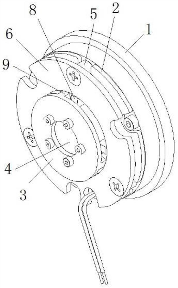
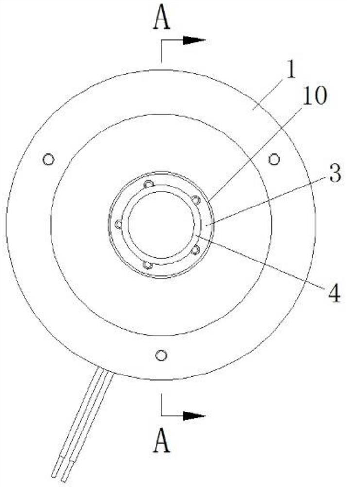
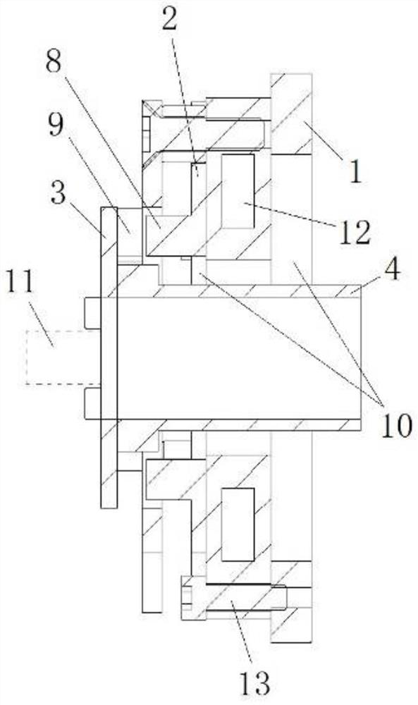
[0038] This embodiment provides a specific implementation of the brake, such as figure 1 As shown, including: brake stator 1, brake plate 2 and brake rotor 3. Wherein, the brake rotor 3 is suitable for being fixedly connected with the rotating shaft 4 of the rotating device, specifically, the fixed connection can be made through the structure of fasteners and flanges, or can be fixedly connected through welding. The brake plate 2 can be slidably arranged on the brake stator 1 in the axial direction. Specifically, the brake stator 1 is provided with a guide column 5, and the other end of the guide column 5 is connected to a fixed disk 6 to make The moving plate 2 is slidably connected to the guide post 5 . The brake plate 2 is opposite to the brake rotor 3 and kept spaced, as Figure 4 As shown, the brake plate 2 has a notch 7 for accommodating the guide post 5 , and a plurality of guide posts 5 are snapped into the notch 7 to guide the brake plate 2 . The brake plate 2 also...

Embodiment 2

[0046] This embodiment provides a specific implementation of a rotating device, which can be used in a joint module of a collaborative robot.

[0047] Such as Image 6 As shown, the rotating device includes: a housing 14 having a shaft chamber 15 for installing the shaft 4 and a brake chamber 16 communicating with the shaft chamber 15 in the axial direction. A rotating shaft 4 is installed in the rotating shaft chamber 15, and one end of the rotating shaft 4 protrudes from the rotating shaft chamber 15 into the brake chamber 16; the brake described in Embodiment 1 is installed in the brake chamber 16, The rotating shaft 4 protrudes from the rotating shaft cavity 15 and is fixedly connected with the brake rotor 3 of the brake.

[0048] Specifically, the brake stator 1 of the brake is installed on the side of the brake cavity 16 close to the shaft cavity 15 by fasteners, and the brake stator 1 has a through hole 10, which is used for the shaft 4 through. Similarly, the brake ...


PUM


Abstract

The invention provides a brake and a rotating device with the brake, and belongs to the technical field of brakes. The brake comprises a brake stator, a brake plate and a brake rotor, wherein the brake plate and the brake rotor are opposite and are arranged at an interval; the brake plate can be arranged on the brake stator in a sliding mode in the direction close to or away from the brake rotor in the axial direction; after the brake plate slides towards the direction close to the brake rotor, the brake plate is connected with the brake rotor in a clamping manner; and after the brake plate slides in the direction away from the brake rotor, the brake plate and the brake rotor are not clamped. According to the brake provided by the invention, the brake rotor is braked in the mode that the brake plate is connected with the brake rotor in a clamped mode, so that compared with friction braking and clamping braking, too much powder cannot be generated, and the internal environment of a module is ensured to be clean.

Description

technical field [0001] The invention relates to the technical field of brakes, in particular to a brake and a rotating device with the brake. Background technique [0002] The existing brakes for the joint modules of collaborative robots generally adopt electromagnetic friction plate brakes and electromagnetic telescopic brakes. [0003] Among them, the electromagnetic friction plate is made of pressed powder, which is easy to produce grinding powder during braking, causing serious pollution to the internal environment of the module. The electromagnetic telescopic brake is an iron core telescopic, which has the disadvantages of faster temperature rise, lower precision of a single electromagnetic telescopic rod, and a certain angle delay. [0004] In addition, the existing brakes generally have a solid structure. For a module with a small diameter, it needs to occupy a large axial space of the module, which has the disadvantage of being inconvenient to install. Contents of...

Claims


Application Information

Patent Timeline
IPC IPC(8): F16D63/00F16D65/16F16D66/00B25J19/00F16D121/20
CPCF16D63/006F16D63/002F16D65/16F16D66/00B25J19/0004F16D2121/20
Inventor 谭元清董忠李晓华尹红光
Owner GUANGDONG BOZHILIN ROBOT CO LTD
Learn More