
A deep shale gas development method

A shale gas, deep-layer technology, applied in the direction of production fluid, earthwork drilling, wellbore/well components, etc., can solve the problems of operability, reduce injection displacement, and reduce the drag reduction effect of deep shale gas fracturing To achieve the effects of increasing the volume of reservoir stimulation, enhancing the shaping characteristics, improving the level of development technology and economic benefits

Active Publication Date: 2022-04-05
SOUTHWEST PETROLEUM UNIV
View PDF12 Cites 0 Cited by
  • Summary
  • Abstract
  • Description
  • Claims
  • Application Information

AI Technical Summary

Problems solved by technology

Simply reducing the concentration of the thickener will reduce the drag-reducing effect of deep shale gas fracturing, and the drag-reducing effect is a crucial parameter, which cannot be lowered easily, otherwise, the injection displacement of fracturing construction will be greatly reduced , complex cracks cannot be realized
But instead of emulsion-type slick water, the application of the two kinds of slick water in the field, the corresponding injection equipment and supporting procedures are quite different, and there are problems in the operability of the field implementation, which will also cause deep shale gas fracturing. Bringing risks and uncertainties to construction
More importantly, the viscosity of emulsion-type slick water is also as high as 2-3 mPas, which may still be too high for deep shale gas fracturing, making it difficult to further communicate and extend more small micro-scale fracture systems
Therefore, neither the powder type nor the emulsion type slick water is suitable for deep shale gas well fracturing

Method used

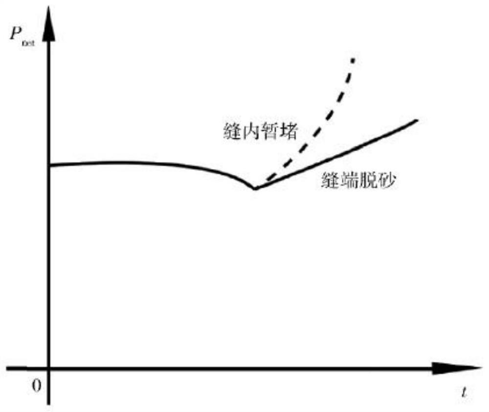
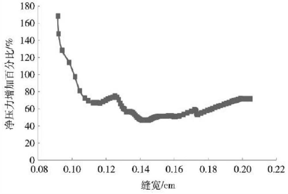
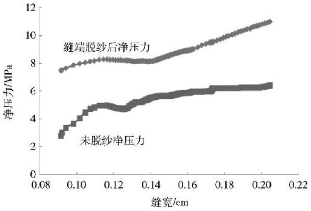

Image

  • A deep shale gas development method
  • A deep shale gas development method
  • A deep shale gas development method

Examples


Embodiment Construction

[0024] In the following, the technical solutions in the present invention will be fully described in conjunction with the accompanying drawings in the embodiments of the present invention. Obviously, the described embodiments are only some of the embodiments of the present invention, not all of them. Based on the present invention All other embodiments obtained by those skilled in the art without creative efforts, all belong to the protection scope of the present invention.

[0025] A method for developing deep oil shale gas, comprising the following steps: step (2), at first drilling three horizontal wells away from the water layer and fault zone; step (3), utilizing acid liquid to pretreat the wellbore at the perforation place; step (4), large-scale fracturing by using the horizontal section; in step (5), the sequence of injected fluid types is medium-viscosity slick water + low-viscosity acid + medium-viscosity glue, the medium-viscosity slick water, low-viscosity acid Both...


PUM


Abstract

The invention discloses a method for developing deep shale gas, which comprises the following steps: step (1) evaluates the gas content of shale gas, and establishes and analyzes the relationship between the gas content and the natural gas occurrence state; step (2) in Drill three horizontal wells away from the water layer and fault zone; step (3), first perform mechanical segmentation on the three horizontal wells and complete perforation in the segment, and then use acid fluid to pretreat the wellbore at the perforation; step (4), use Large-scale fracturing in the horizontal section; in step (5), the fluid types to be injected are in the order of medium-viscosity slick water, low-viscosity acid fluid, and medium-viscosity fluid. The material undergoes a violent redox reaction; in step (6), after the high-pressure mixed gas is purified and separated from the gas production wells in the vertical section and the horizontal section, oil and fuel materials can be obtained, which can be further processed according to product requirements. The application of this invention makes the economical and effective development of deep shale gas possible. It is an important breakthrough in the technical field of shale gas methods and has great significance for improving the development technology level and economic benefits of unconventional oil and gas reservoirs.

Description

technical field [0001] The invention relates to the field of oil and gas reservoir development, in particular to a deep shale gas development method. Background technique [0002] At present, with the deepening of shale gas exploration and development, the probability of occurrence of deep complex shale gas is increasing. The so-called "complex shale gas" refers to shale gas reservoirs with a carbonate rock content of more than 20% in lithology and a large number of horizontal bedding fractures, texture fractures and high-angle natural fractures (filled or unfilled) structurally , its complexity can easily lead to out-of-control fracture height of fracturing fractures, and then the net pressure of main fractures is greatly reduced, and it is difficult to achieve the goal of volume fracturing. substantially restricted. In terms of three-dimensional stress characteristics, due to the extrusion of tectonic stress, the minimum horizontal principal stress may be close to the ve...

Claims


Application Information

Patent Timeline
Patent Type & Authority Patents(China)
IPC IPC(8): E21B43/00E21B43/26E21B43/267E21B47/00E21C41/24G06Q50/02
CPCE21B43/006E21C41/24E21B43/26E21B43/267E21B47/00G06Q50/02
Inventor 巫晓兵贾旭张超李小刚李昆成
Owner SOUTHWEST PETROLEUM UNIV
Learn More