
Optical module device

A technology of optical modules and optical signals, applied in the direction of electromagnetic transceivers, etc., can solve the problems of reducing optical demultiplexers and optical detectors, power loss, etc.

Inactive Publication Date: 2021-05-18
SHUNYUN TECH (ZHONG SHAN) LTD
View PDF6 Cites 0 Cited by
  • Summary
  • Abstract
  • Description
  • Claims
  • Application Information

AI Technical Summary

Problems solved by technology

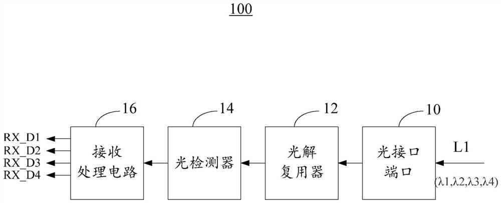
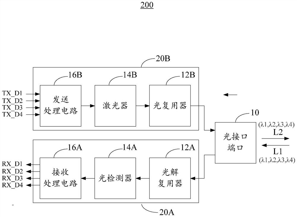
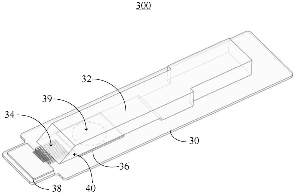
[0003] In view of this, in one embodiment of the present invention, by reducing the distance between the optical demultiplexer and the photodetector, the problems of light spot generation and power loss caused by optical path difference are solved

Method used


Image

  • Optical module device
  • Optical module device
  • Optical module device

Examples


Embodiment Construction

[0040] In order to facilitate those skilled in the technical field of the present invention to understand and implement the present invention, the present invention will be described in further detail below in conjunction with the accompanying drawings and embodiments. It should be understood that the present invention provides many applicable inventive concepts, which can be implemented in various specific forms . Those skilled in the technical field of the present invention can use the details described in these embodiments or other embodiments and other available structural, logical and electrical changes to implement the invention without departing from the spirit and scope of the present invention.

[0041] The description of the present invention provides different examples to illustrate the technical features of different implementations of the present invention. Wherein, the configuration of each element in the embodiment is for illustration, not for limiting the prese...


PUM


Abstract

An optical module device includes a substrate, an optical detector, a supporting device, and an optical demultiplexer. The optical detector is arranged on the substrate and used for detecting light signals and generating corresponding electric signals. The supporting device is arranged on the substrate, and a gap is formed between the supporting device and the light detector. The optical demultiplexer is bonded with the supporting device through glue and is in direct contact with the optical detector. According to the embodiment of the invention, the distance between the optical demultiplexer and the optical detector is reduced, so that the problem of power loss caused by light spot generation and optical path difference loss is solved.

Description

technical field [0001] The invention relates to an optical module device, in particular to an optical module device for receiving optical signals. Background technique [0002] Optical transceivers are used to transmit and receive optical signals for various applications, including Internet data centers, cable television broadband, and fiber to the home (FTTH) applications, among others. An optical transceiver may include one or more optical transmitting assemblies (transmitter optical subassemblies, TOSA) and optical receiving assemblies (receiver optical subassemblies, ROSA) for transmitting and receiving optical signals. In the optical receiving component, when the optical signal is transmitted from the optical demultiplexer to the optical detector, the generation of light spots and the power loss caused by the optical path difference must be considered. Contents of the invention [0003] In view of this, in one embodiment of the present invention, by reducing the dist...

Claims


Application Information

Patent Timeline
IPC IPC(8): H04B10/40
CPCH04B10/40
Inventor 鲍勇年
Owner SHUNYUN TECH (ZHONG SHAN) LTD
Learn More