Eureka AIR delivers breakthrough ideas for toughest innovation challenges, trusted by R&D personnel around the world.

Barren rock and tailing mixed slurry preparation and pumping filling device

A technology for mixing slurry and filling equipment, which is applied in the direction of mixing operation control equipment, clay preparation equipment, mixing operation control, etc., and can solve problems such as limited supply of waste rock, difficulty in dust control, and difficulty in replacing large-scale stope filling.

Pending Publication Date: 2021-05-18
CENT SOUTH UNIV +1
View PDF0 Cites 7 Cited by
  • Summary
  • Abstract
  • Description
  • Claims
  • Application Information

AI Technical Summary

Problems solved by technology

[0006] At the same time, in most mines mined by the filling method, if only waste rock tailings mixed slurry is pumped for filling, it is generally difficult to replace the existing filling system for large-scale stope filling due to the limited pumping capacity and waste rock supply.
In some domestic mines, such as Hebei Yuer Gold Mine, a complete set of automatic continuous pumping and filling technical equipment adapted to the underground environment has been designed, and the residual ore resource mining test has been carried out. However, because the cement material cement is fed underground, the transportation efficiency is low and the The filling capacity of the underground filling system does not match, the equipment utilization rate is low, and the dust control is difficult, etc.

Method used


Image

  • Barren rock and tailing mixed slurry preparation and pumping filling device
  • Barren rock and tailing mixed slurry preparation and pumping filling device
  • Barren rock and tailing mixed slurry preparation and pumping filling device

Examples


Embodiment Construction

[0030]The following will clearly and completely describe the technical solutions in the embodiments of the present invention with reference to the accompanying drawings in the embodiments of the present invention. Obviously, the described embodiments are only some, not all, embodiments of the present invention. Based on the embodiments of the present invention, all other embodiments obtained by persons of ordinary skill in the art without creative efforts fall within the protection scope of the present invention.

[0031] In describing the present invention, it should be understood that the terms "center", "longitudinal", "transverse", "length", "width", "thickness", "upper", "lower", "front", " Back", "Left", "Right", "Vertical", "Horizontal", "Top", "Bottom", "Inner", "Outer", "Clockwise", "Counterclockwise", "Axial", The orientation or positional relationship indicated by "radial", "circumferential", etc. is based on the orientation or positional relationship shown in the d...


PUM


Abstract

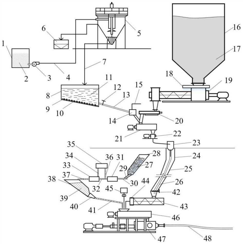
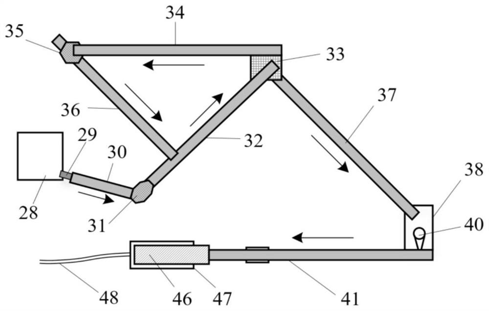
The invention discloses a barren rock and tailing mixed slurry preparation and pumping filling device. The device comprises a slurry preparation system, a barren rock crushing system, a stirring system and a pumping filling system, the slurry preparation system is arranged on the earth surface, and the barren rock crushing system, the stirring system and the pumping filling system are all arranged underground. The slurry preparation system is in butt joint with the feeding end of the stirring system through a self-sliding filling pipeline, the discharging end of the barren rock crushing system is in butt joint with the feeding end of the stirring system, the pumping filling system is in butt joint with a mixed material outlet of the stirring system, the slurry preparation system is used for preparing full-tailing cementing slurry, and the barren rock crushing system is used for crushing underground barren rocks. The device can make full use of the underground barren rocks for cementing filling, can prevent the barren rocks from going out of pits, greatly reduces the transportation and lifting cost of the barren rocks, improves the comprehensive utilization rate of the barren rocks, and achieves the pumping and filling of mixed high-concentration slurry of tailing slurry and the barren rocks in combination with an existing full-tailing cementing filling system.

Description

technical field [0001] The invention relates to the technical field of underground mine filling and mining, in particular to a waste rock and tailing sand mixed slurry preparation and pumping filling device. Background technique [0002] The filling mining method is widely recognized for its advantages of improving resource recovery rate, energy saving and emission reduction, environmental protection, safety and reliability. From the perspective of environmental protection and mining safety, the filling and filling mining method represents one of the development trends of mining technology at home and abroad. Underground mine filling mining technology and technology have experienced from dry filling to hydraulic filling, from low concentration graded tailings cemented filling to full tailings high concentration cemented filling, paste, paste-like body, and waste rock-full tailings high concentration Pipeline filling technology transition. In particular, a lot of research a...

Claims


Application Information

Patent Timeline
IPC IPC(8): E21F15/00E21F15/06E21F13/00B28C9/02B28C7/04B28C7/06B28C7/10B28C7/00B02C21/00B02C23/12
CPCE21F15/005E21F15/06E21F13/00B28C9/02B28C7/04B28C7/0007B28C7/06B28C7/10B02C21/00B02C23/12B02C2201/06
Inventor 高峰周科平梁耀东熊信罗增武艾浩泉
Owner CENT SOUTH UNIV
Why Eureka
Eureka Blog
Learn More