
Combined type vertical take-off and landing long-endurance electric unmanned aerial vehicle

An electric unmanned aerial vehicle, vertical take-off and landing technology, applied in the field of unmanned aerial vehicles, can solve the problems of difficult operation, inability to perform hovering images, and low aerial survey efficiency.

Pending Publication Date: 2021-05-18
NORTHWESTERN POLYTECHNICAL UNIV
View PDF6 Cites 2 Cited by
  • Summary
  • Abstract
  • Description
  • Claims
  • Application Information

AI Technical Summary

Problems solved by technology

For the UAV inspection industry, fixed-wing UAVs have the advantages of fast flight speed, large cruising area, and heavy mission load. Hover to obtain images of a continuous location, and the operation is more difficult
Multi-rotor UAVs are small in size and light in weight, can take off and land vertically without a site, and are easy to operate, but their flight speed is small, the flight distance is short, and the efficiency for aerial surveys is very low
The composite UAV has the advantages of both fixed-wing and rotary-wing UAVs. It can not only realize the vertical take-off and landing function without site requirements, but also realize fixed-point hovering to obtain continuous images of a certain place, and can also carry loads. And the flight speed is fast, the cruising distance is long, and the inspection efficiency is high. However, due to the limitation of aircraft batteries, the battery life of the common composite vertical take-off and landing drones on the market is about 60 to 100 minutes, which makes it difficult for long-distance , when performing large-scale inspection missions, multiple sorties have to be used to complete the mission, so how to improve the endurance time of UAVs is of great significance

Method used


Image

  • Combined type vertical take-off and landing long-endurance electric unmanned aerial vehicle
  • Combined type vertical take-off and landing long-endurance electric unmanned aerial vehicle
  • Combined type vertical take-off and landing long-endurance electric unmanned aerial vehicle

Examples


Embodiment Construction

[0027] In order to enable those skilled in the art to better understand the solutions of the present invention, the following will clearly and completely describe the technical solutions in the embodiments of the present invention in conjunction with the drawings in the embodiments of the present invention. Obviously, the described embodiments are only It is an embodiment of a part of the present invention, but not all embodiments. Based on the embodiments of the present invention, all other embodiments obtained by persons of ordinary skill in the art without making creative efforts shall fall within the protection scope of the present invention.

[0028] It should be noted that the terms "first" and "second" in the description and claims of the present invention and the above drawings are used to distinguish similar objects, but not necessarily used to describe a specific sequence or sequence. It is to be understood that the data so used are interchangeable under appropriate ...


PUM


Abstract

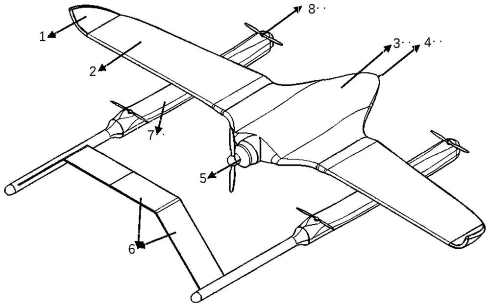
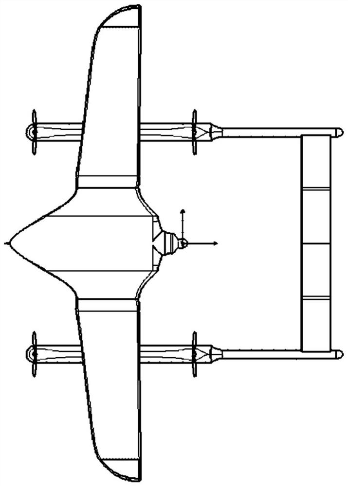
The invention discloses a combined type vertical take-off and landing long-endurance electric unmanned aerial vehicle, which belongs to the field of unmanned aerial vehicles. According to the combined type vertical take-off and landing long-endurance electric unmanned aerial vehicle, the fuselage adopts the wing body fusion body, the wetted area of the unmanned aerial vehicle can be reduced by removing unnecessary exposed parts of the fuselage, so that the frictional resistance is reduced, and the lift-drag ratio of the unmanned aerial vehicle is increased by reducing parts irrelevant to lift force in the wing body fusion layout. The winglet is adopted, the end plate effect of the winglet is utilized, and the equivalent aspect ratio of the aircraft is increased under the condition that the wingspan increase is small. The double-tail-boom empennage layout is adopted, the lateral stability of the unmanned aerial vehicle can be improved, and the structural support is good. The lift-drag ratio aerodynamic layout is improved through the structural design of the unmanned aerial vehicle, so that the endurance performance of the aircraft is improved.

Description

technical field [0001] The invention belongs to the field of unmanned aerial vehicles, in particular to a composite vertical take-off and landing long-endurance electric unmanned aerial vehicle. Background technique [0002] In the past ten years, UAV-related technologies have developed rapidly. UAVs have gradually entered the public's field of vision from the original military field, and they have shined brilliantly in the civilian field. With the joining of a large number of researchers, there are more and more types of unmanned aerial vehicles, such as fixed-wing UAVs, rotary-wing UAVs, composite UAVs, etc., and their uses are becoming more and more extensive, widely used in agriculture, forestry, plant protection, power Inspection, meteorological observation, urban environmental monitoring, express freight, aerial photography, etc. For the UAV inspection industry, fixed-wing UAVs have the advantages of fast flight speed, large cruising area, and heavy mission load. Hov...

Claims


Application Information

Patent Timeline
Patent Type & Authority Applications(China)
IPC IPC(8): B64C27/26B64C27/28B64C3/10B64D27/24
CPCB64C27/26B64C27/28B64C3/10B64D27/24B64U50/19Y02T50/60
Inventor 刘贞报梁盟博江飞鸿严月浩张军红赵闻
Owner NORTHWESTERN POLYTECHNICAL UNIV
Learn More