
A valley-filling and flicker-free pfc converter

A converter and flicker-free technology, which is applied in the direction of converting DC power input to DC power output, instruments, and adjusting electrical variables, etc. It can solve the problems of short service life, large overall volume, and the inability to select the valley filling time of ordinary valley filling circuits, etc. problems, to achieve the effect of increasing service life, reducing overall volume and improving practical value

Active Publication Date: 2021-11-05
SHENZHEN YUANNENG ELECTRIC CO LTD
View PDF5 Cites 0 Cited by
  • Summary
  • Abstract
  • Description
  • Claims
  • Application Information

AI Technical Summary

Problems solved by technology

[0002] In order to provide stable energy output, the existing converters usually perform filtering after AC rectification, but when the capacitor is directly added, the capacitor voltage decreases with the AC input as the load increases, which reduces the effect of the capacitor; ordinary valley-filling circuits, Valley filling requires capacitors to be charged in series and discharged in parallel. The number of capacitors must be at least two or more, and ordinary valley filling circuits cannot choose the time of valley filling.
[0003] Furthermore, in a single-stage PFC circuit, in order to increase the PF value, the current and voltage need to be in the same phase. Therefore, when the sine wave is at a low point in the prior art, the output power of the converter designed is low or even no output, resulting in a load on the output When the current and voltage ripple is large, there is a strobe when using it on the LED lamp
Moreover, the service life of the components inside the existing converter is relatively short, the overall volume is large, there is less room for capacitor selection, the limited control of the circuit is low, the output efficiency is not high and not stable enough

Method used


Image

  • A valley-filling and flicker-free pfc converter
  • A valley-filling and flicker-free pfc converter
  • A valley-filling and flicker-free pfc converter

Examples


Embodiment Construction

[0054] In order to make the above objects, features and advantages of the present invention more comprehensible, specific implementations of the present invention will be described in detail below in conjunction with the accompanying drawings. In the following description, numerous specific details are set forth in order to provide a thorough understanding of the present invention. However, the present invention can be implemented in many other ways different from this description, and those skilled in the art can make similar improvements without departing from the connotation of the present invention, so the present invention is not limited by the specific embodiments disclosed below.

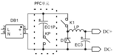
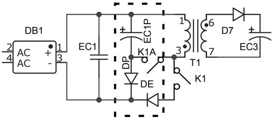
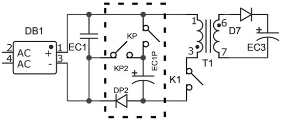
[0055] The invention discloses a valley-filling and flicker-free PFC converter, which is characterized in that it is divided into the following units:

[0056] An input unit, the input unit is any one of an input capacitor, an input AC rectified bus bar, an AC rectified plus filter capacitor,...


PUM


Abstract

The invention discloses a valley-filling and flicker-free PFC converter, which includes: a PFC unit, the PFC unit is provided with an energy storage capacitor and at least one switch tube, and the PFC unit is electrically connected in front of a wave circuit or a converter , and charge through the bus input terminal and / or winding flyback; by combining the PFC unit with other circuits and the corresponding control method, the peak energy is stored in the PFC unit at a certain moment to increase the PF value, and the PFC unit can be used as needed. Release and fill the valley to prevent output fluctuations; control the PFC unit for energy storage and release control through the internal light switch and / or diode, and when the PFC module is added between the windings, the energy storage capacitance in the PFC unit can be controlled at a low level Lower the withstand voltage of the PFC capacitor; achieve stable output and no flicker, reduce the internal components used, thereby reducing the overall volume of the converter, while increasing the service life.

Description

technical field [0001] The invention relates to the field of converter equipment, in particular to a valley-filling and flicker-free PFC converter. Background technique [0002] In order to provide stable energy output, the existing converters usually perform filtering after AC rectification, but when the capacitor is directly added, the capacitor voltage decreases with the AC input as the load increases, which reduces the effect of the capacitor; ordinary valley-filling circuits, Valley filling requires capacitors to be charged in series and discharged in parallel. The number of capacitors must be at least two or more, and ordinary valley filling circuits cannot choose the time of valley filling. [0003] Furthermore, in a single-stage PFC circuit, in order to increase the PF value, the current and voltage need to be in the same phase. Therefore, when the sine wave is at a low point in the prior art, the output power of the converter designed is low or even no output, resul...

Claims


Application Information

Patent Timeline
Patent Type & Authority Patents(China)
IPC IPC(8): H02M1/42H02M1/14H02M3/156H02M3/335
CPCH02M1/4258H02M1/4225H02M1/4208H02M1/14H02M3/156H02M3/33523H02M3/33576H02M3/33569Y02B70/10
Inventor 严宗周
Owner SHENZHEN YUANNENG ELECTRIC CO LTD
Learn More