Smoke alarm with spraying function

A technology of smoke alarm and function, which is applied in the direction of fire alarm and fire rescue based on the effect of smoke/gas, and can solve the problems of not being able to sense smoke at the first time, not being protected, and burning

Active Publication Date: 2021-05-14
徐丹
View PDF8 Cites 7 Cited by
  • Summary
  • Abstract
  • Description
  • Claims
  • Application Information

AI Technical Summary

Problems solved by technology

[0002] The smoke alarm is usually installed on the ceiling of the house. When a fire breaks out, the smoke diffuses into the smoke alarm on the ceiling and sends a signal after detecting the smoke. However, due to the poor air circulation of the house, when a fire breaks out in the house, It takes a long time for the smoke to diffuse to the position of the smoke alarm, which reduces the reliability of the smoke alarm to a certain extent and cannot sense the smoke in the first place
At the same time, after the smoke alarm is installed on the ceiling of the house, due to the inconsistent height of the room space, the smoke rising from the fire source on the ground of the house cannot quickly reach the position where the detection sensor seat is located, making the induction effect not ideal, which will lead to detection The induction time is too long, so reasonable smoke alarms should be improved in structure to increase the induction speed and make the alarm earlier
[0003] The smoke alarm is installed on the ceiling of the house, and is usually exposed vertically to the outside. When an indoor fire occurs, it can only be used as an alarm, and it cannot be protected by itself. When the indoor temperature is too high, it will be melted. or scorched, causing damage to the device

Method used


Image

  • Smoke alarm with spraying function
  • Smoke alarm with spraying function
  • Smoke alarm with spraying function

Examples


Embodiment Construction

[0020] Preferred embodiments of the present invention will be described in detail with reference to the accompanying drawings so that those embodiments can be easily realized by those having ordinary skill in the art to which the invention pertains. However, the present invention can also be realized in various forms, so the present invention is not limited to the embodiments described hereinafter. In addition, in order to describe the present invention more clearly, parts not connected with the present invention will be omitted from the drawings.

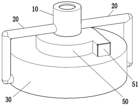
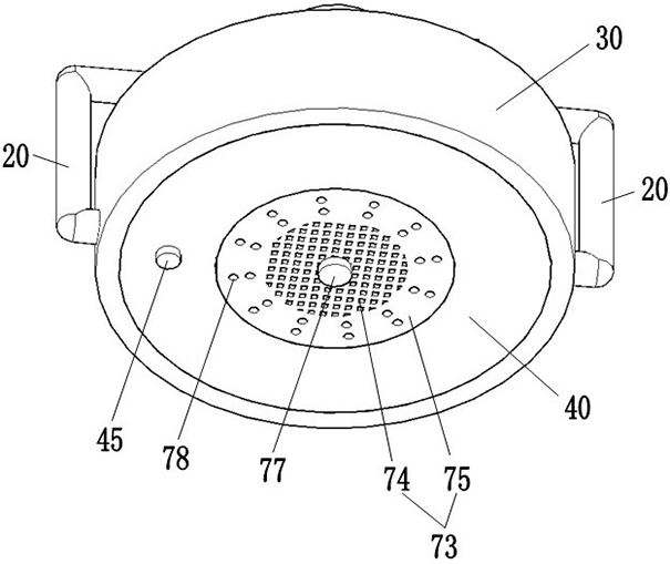
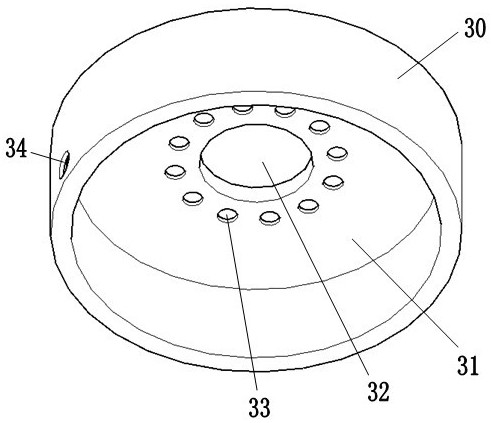
[0021] Such as figure 1 , figure 2 as well as Figure 6 As shown, a smoke alarm with spray function includes: electromagnetic valve 10, connecting pipe 20, water tank 30, main control room 40, centrifugal fan 50, detection room 60 and air pipe 70; wherein electromagnetic valve 10 is a Water inlet and two water outlet structures, the whole device is vertically connected on the fire water pipe on the roof of the house through the...


PUM


Abstract

The invention relates to the technical field of fire fighting equipment, in particular to a smoke alarm with a spraying function. The smoke alarm comprises an electromagnetic valve, a connecting pipe, a water tank, a main control room, a centrifugal fan, a detection room and an air pipe; the main control chamber is mounted in the mounting groove of the water tank, and the air pipe penetrates out of the middle of the main control chamber, so that equipment damage caused by equipment melting or scorching due to too high indoor temperature in a fire disaster can be effectively avoided; meanwhile, when the temperature sensor detects that the smoke exceeds a preset threshold value, a signal is sent to the controller, the controller controls the centrifugal fan to start and the button to bounce, so that the two electromagnets are powered off, the folded air pipe falls and is opened under the action of gravity, the air pipe can suck smoke at a lower height into the detection chamber, the sensing speed of smoke detection is increased, alarming is advanced, and the centrifugal fan only works when detection is needed, so that resources are effectively saved.

Description

technical field [0001] The invention relates to the technical field of fire fighting equipment, in particular to a smoke alarm with a spray function. Background technique [0002] The smoke alarm is usually installed on the ceiling of the house. When a fire breaks out, the smoke diffuses into the smoke alarm on the ceiling and sends a signal after detecting the smoke. However, due to the poor air circulation of the house, when a fire breaks out in the house, It takes a long time for the smoke to diffuse to the position of the smoke alarm, which reduces the reliability of the smoke alarm to a certain extent and cannot sense the smoke at the first time. At the same time, after the smoke alarm is installed on the ceiling of the house, due to the inconsistent height of the room space, the smoke rising from the fire source on the ground of the house cannot quickly reach the position where the detection sensor seat is located, making the induction effect not ideal, which will lead...

Claims


Application Information

Patent Timeline
Patent Type & Authority Applications(China)
IPC IPC(8): G08B17/10A62C31/00A62C37/40
CPCG08B17/10A62C31/005A62C37/40
Inventor 林帅
Owner 徐丹
Why Eureka
Try Eureka