
Transmission mechanism for automatic thread rolling machine

A technology of a transmission mechanism and a thread rolling machine, which is applied in the cleaning method, transmission device, application, etc. using gas flow, can solve the problem that the transmission mechanism cannot be linked with the whole device, the metal debris is mixed in the thread rolling plate, and the single power Transfer the thread rolling mechanism and other issues to achieve the effect of complete product production process, improve product processing quality, and reduce processing procedures

Inactive Publication Date: 2021-05-14
南通振馨芫纺织品有限公司
View PDF0 Cites 1 Cited by
  • Summary
  • Abstract
  • Description
  • Claims
  • Application Information

AI Technical Summary

Problems solved by technology

[0005] 1. The transmission mechanism of the thread rolling machine only transmits the power to the thread rolling mechanism, and cannot link the transmission mechanism with the whole device well, and the realized function is too single;
[0006] 2. When the thread rolling machine is in use, the metal debris generated by the thread rolling is easy to be mixed in the thread rolling plate. If it is not removed in time, it is easy to cause damage to the post-processed products and directly lead to the scrapping of the products;
[0007] 3. The parts that have been finished by thread rolling are piled up at the bottom of the device, which is easy to hinder the parts processed later. Manual cleaning has certain dangers and is easy to cause injury to the staff.

Method used


Image

  • Transmission mechanism for automatic thread rolling machine
  • Transmission mechanism for automatic thread rolling machine
  • Transmission mechanism for automatic thread rolling machine

Examples


Embodiment Construction

[0029] The following will clearly and completely describe the technical solutions in the embodiments of the present invention with reference to the accompanying drawings in the embodiments of the present invention. Obviously, the described embodiments are only some, not all, embodiments of the present invention. Based on the embodiments of the present invention, all other embodiments obtained by persons of ordinary skill in the art without making creative efforts belong to the protection scope of the present invention.

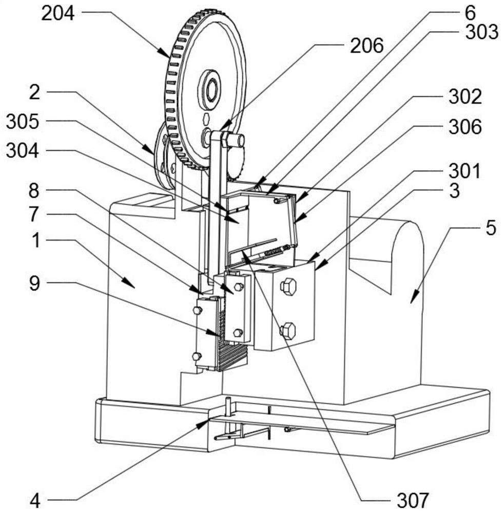
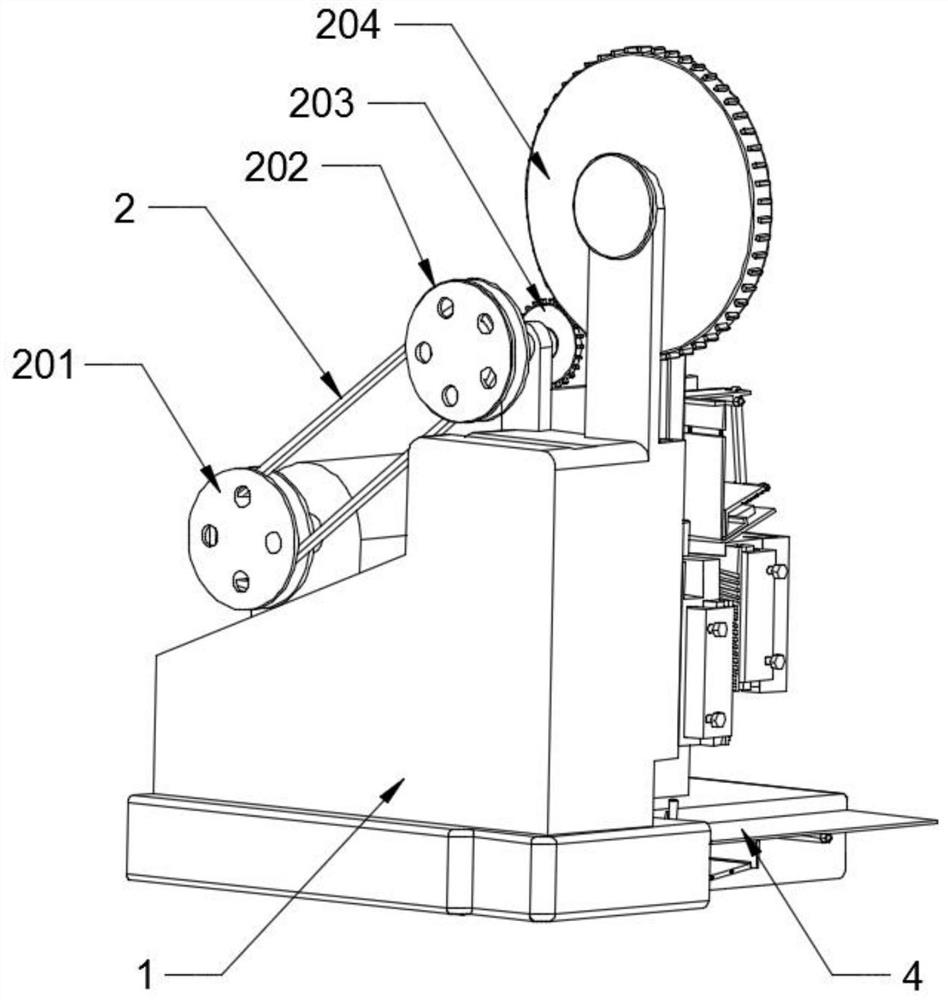
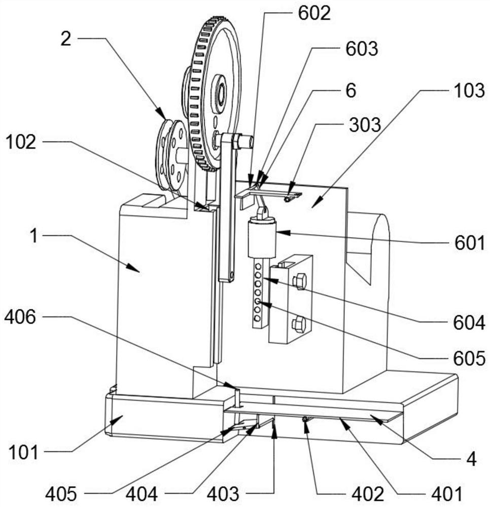
[0030] Please also refer to Figure 1-Figure 6 , wherein, a transmission mechanism for an automatic thread rolling machine includes a support mechanism 1, a power mechanism 2 and a body 5, the power mechanism 2 is fixedly installed on the top of the support mechanism 1, and the body 5 is arranged on the support mechanism 1 close to the power mechanism 2- side, the support mechanism 1 is fixedly installed with a cleaning mechanism 6 on the side of the body 5, t...


PUM


Abstract

The invention discloses a transmission mechanism for an automatic thread rolling machine. The transmission mechanism comprises a supporting mechanism, a power mechanism and a machine body, wherein the power mechanism is fixedly installed at the top end of the supporting mechanism, the machine body is arranged on the side, close to the power mechanism, of the supporting mechanism, a cleaning mechanism is fixedly installed on the portion, on the side face of the machine body, of the supporting mechanism, a sliding mechanism is slidably connected to the side face of the supporting mechanism, a switching mechanism is fixedly welded to the side, close to the machine body, of the supporting mechanism, a fixing mechanism is fixedly installed on the side face of the switching mechanism, a material guiding mechanism is arranged at the position, under the sliding mechanism and the fixing mechanism, of the bottom end of the supporting mechanism, and thread rolling plates are fixedly connected to the side faces of the sliding mechanism and the fixing mechanism in a clamped mode. When the transmission mechanism is used, the transmission mechanism is linked with other parts in the thread rolling process, more effects are achieved, the product machining quality of the device is improved, the device is easier to use, and the part machining efficiency is higher.

Description

technical field [0001] The invention relates to the technical field of thread rolling machines, in particular to a transmission mechanism for automatic thread rolling machines. Background technique [0002] Thread rolling machine is an equipment specialized in the production of screws. Define the thread rolling machine, which is the equipment specialized in the production of screws. Thread rolling machine, there are various specifications of thread rolling machines, such as automatic thread rolling machine, flat plate thread rolling machine, semi-automatic thread rolling machine, automatic thread rolling machine, high-speed thread rolling machine, etc.; [0003] Transmission refers to the power transmission between machines. It can also be said that the mechanical power is transmitted to the terminal equipment through an intermediate medium. This transmission mode includes chain transmission, friction transmission, hydraulic transmission, gear transmission and belt transmis...

Claims


Application Information

Patent Timeline
IPC IPC(8): B21H3/06B08B5/02F16H37/12
CPCB08B5/02B21H3/06F16H37/12
Inventor 不公告发明人
Owner 南通振馨芫纺织品有限公司
Learn More