


Quick Research
Generate reliable direction feasibility study reports for your R&D in just a few steps.

Technical Q&A
Discover and master advanced knowledge NOW. Basics, ideas, possibilities, all at once.

Find Solutions
As an expert in R&D theories, this can generate solutions to your technical problems instantly.

Evaluate Feasibility
Analyze your overall solution with one click, know your potential R&D risks in advance.

Monitor Landscape
Get weekly tech updates, stay abreast of the latest tech innovations and key insights.
Clamping and conveying mechanism and device
A technology of conveying mechanism and clamping rod, applied in the direction of conveyor objects, transportation and packaging, etc., can solve the problem of large space occupation, and achieve the effect of eliminating damage, convenient maintenance and simple structure
- Summary
- Abstract
- Description
- Claims
- Application Information
AI Technical Summary
Problems solved by technology
Method used
Image

Examples
Embodiment 1
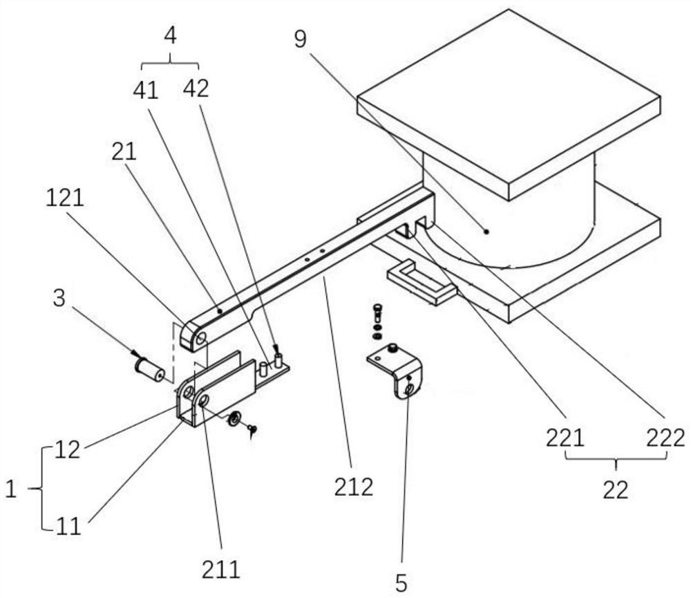
[0030] An embodiment of the present invention provides a clamping and conveying mechanism, which includes a base 1 and a clamping rod 2 rotatably connected to the base 1 . The base 1 is a U-shaped groove structure, which is integrally formed by a bottom plate 11 and two vertical plates 12 . Axial holes 121 are respectively opened on the two vertical plates 12, and the two axial holes 121 are arranged coaxially. The clamping rod 2 includes an F-shaped structural rod formed by a rod body 21 and a splint 22. Specifically, the splint 22 includes a first splint 221 and a second splint 222. The first splint 221 and the second splint 222 are spaced apart from each other and parallel to each other. Connected to the same side of the rod body 21. Preferably, after the connection, the first clamping plate 221 is flush with the end surface of the rod body 21 , and the second clamping plate 222 is a certain distance away from the first clamping plate 221 , and the two form an inverted U-s...
Embodiment 2
[0036] This embodiment 2 is formed on the basis of embodiment 1. By setting the support assembly, the clamping plate can be kept at a predetermined height, preventing the clamping plate at the front end of the clamping rod from being hooked with the object due to the downward extension. At the same time, by further Optimized design eliminates damage caused by hard contact falling back during clamp lever unlocking. specifically:
[0037] The support assembly 4 includes a connection plate 41 and a support column 42 connected to the connection plate 41 , the support column 42 is a column structure, preferably fixed on the connection plate 41 in a vertical manner. The connecting plate 41 is connected to the bottom plate 11 through welding or screwing, and the connecting plate 41 is located on the bottom plate 11 and extends toward the clamping plate 2 . The support column 42 is at a certain distance from the bearing pin, and the clamping rod 2 is used as a fulcrum for rotation by...
Embodiment 3
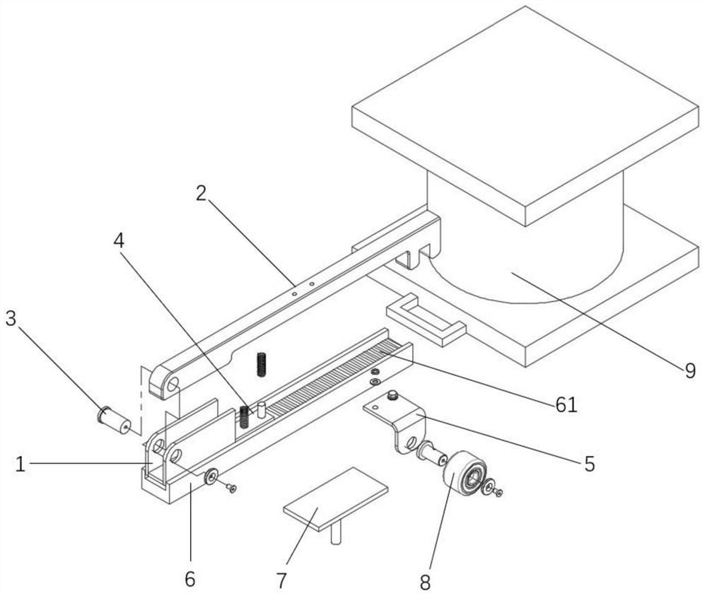
[0041]This embodiment 3 is a clamping and conveying device formed on the basis of embodiment 1 or embodiment 2, including the clamping and conveying mechanism in any embodiment of embodiment 1 or embodiment 2, and also includes a slide rail 6 And jacking mechanism 7. Slide rail 6 is designed as groove structure, and the groove of its slide rail 6 is provided with transmission chain 61, and transmission chain 61 can do linear reciprocating motion in slide rail 6. The part of the base 1 is placed in the groove of the slide rail 6, and its bottom plate is connected with the transmission chain 61. The linear reciprocating motion of the transmission chain 61 drives the reciprocating movement of the clamping and transporting mechanism to achieve the purpose of clamping and transporting objects. The jacking mechanism 7 comprises a top plate and a power unit (the power unit is not shown in the figure), and the power unit is used to move up and down the top plate, and the top plate is ...
PUM
 Abstract
Description
Claims
Application Information
 - R&D Engineer
- R&D Manager
- IP Professional
- Industry Leading Data Capabilities
- Powerful AI technology
- Patent DNA Extraction
Browse by: Latest US Patents, China's latest patents, Technical Efficacy Thesaurus, Application Domain, Technology Topic, Popular Technical Reports.
© 2024 PatSnap. All rights reserved.Legal|Privacy policy|Modern Slavery Act Transparency Statement|Sitemap|About US| Contact US: help@patsnap.com