Cylindrical wrench

A wrench and barrel-shaped technology, applied in the field of mechanical equipment tools, can solve problems such as difficult disassembly and assembly

Pending Publication Date: 2021-05-11
11TH RES INST OF CHINA ELECTRONICS TECH GROUP CORP
View PDF0 Cites 1 Cited by
  • Summary
  • Abstract
  • Description
  • Claims
  • Application Information

AI Technical Summary

Problems solved by technology

[0003] The embodiment of the present invention provides a cylindrical wrench, which is used to solve the problem in the prior art that it is not easy to disassemble if there is no external force point on one side when the thin-walled cylindrical parts are threaded.

Method used


Image

  • Cylindrical wrench
  • Cylindrical wrench
  • Cylindrical wrench

Examples


Embodiment Construction

[0023] Exemplary embodiments of the present disclosure will be described in more detail below with reference to the accompanying drawings. Although exemplary embodiments of the present disclosure are shown in the drawings, it should be understood that the present disclosure may be embodied in various forms and should not be limited by the embodiments set forth herein. Rather, these embodiments are provided for more thorough understanding of the present disclosure and to fully convey the scope of the present disclosure to those skilled in the art.

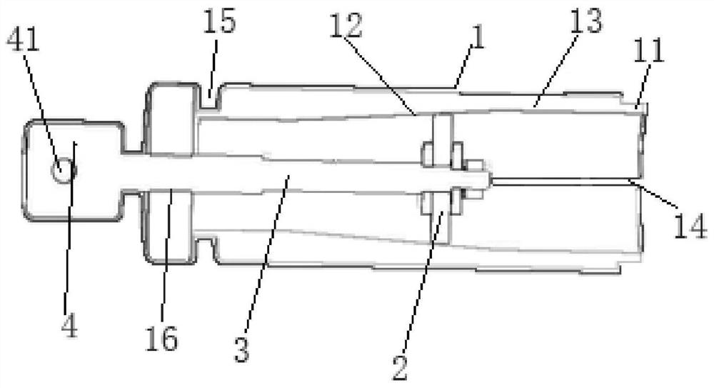
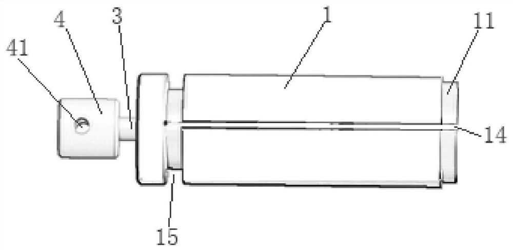
[0024] An embodiment of the present invention provides a cylindrical wrench, such as figure 2 As shown, it includes: cylinder 1, expansion plug 2 and tie rod 3;

[0025] The expansion plug 2 is arranged in the cylinder body 1;

[0026] One end of the tie rod 3 is fixed to the expansion plug 2, and the other end extends out of the cylinder body 1;

[0027] The barrel 1 is provided with a preset number of cutting slits 14 along th...


PUM

PropertyMeasurementUnit
Lengthaaaaaaaaaa

Abstract

The invention discloses a cylindrical wrench which comprises a cylinder 1, an expansion plug 2 and a pull rod 3. The expansion plug 2 is arranged in the cylinder 1. One end of the pull rod 3 is fixed with the expansion plug 2, and the other end of the pull rod 3 extends out of the cylinder1. A preset number of cutting seams 14 are formed in the cylinder 1 in the axial direction, and a conical surface 12 is further arranged on the inner wall of the cylinder 1. One end of the cylinder 1 is provided with a cylinder opening 11, and the expansion plug 2 can be driven by the pull rod 3 to move along the conical surface 12 so as to change the size of the cylinder opening 11. The cylinder opening is formed in one end of the cylinder , the expansion plug is driven by the pull rod to move along the conical surface, the effect of changing the size of the cylinder opening is achieved, the wrench effect is achieved, and therefore the problem that in the prior art, when thin-wall barrel-shaped pieces are in threaded connection, disassembly and assembly are not easy is solved.

Description

technical field [0001] The invention relates to the field of mechanical equipment tools, in particular to a cylindrical wrench. Background technique [0002] With the development of miniaturization of electronic equipment structure, the design of photoelectric sight products is increasingly required to be small in size and light in weight, such as figure 1 As shown, the design of the joint of the lens barrel is getting thinner and thinner. During the production process, the difficulty of disassembly and assembly also increased when the two lens barrels were screwed together. Such as figure 1 As shown, it is necessary to connect the first connecting part 101 to the second connecting part 102 during the disassembly process, because the force area is too small, and there is no suitable assembly tool, so it can only be tightened or loosened directly by hand, resulting in inconsistent tightness. The lens barrel is easy to deform, which often leads to quality problems of the pr...

Claims


Application Information

Patent Timeline
IPC IPC(8): B25B13/10B25B23/00
CPCB25B13/10B25B23/00
Inventor 郝利民贾金山阚博涵
Owner 11TH RES INST OF CHINA ELECTRONICS TECH GROUP CORP
Why Eureka
Try Eureka