Withdrawal and straightening machine for washing machine drum manufacturing

A technology of washing machine drum and tension leveler, applied in the field of tension leveler, can solve the problems of cumbersome leveling process, long leveling time for iron sheets in the inner drum of the washing machine, different specifications, etc.

Inactive Publication Date: 2021-05-11
浙江宏泰精密科技有限公司
View PDF0 Cites 0 Cited by
  • Summary
  • Abstract
  • Description
  • Claims
  • Application Information

AI Technical Summary

Problems solved by technology

[0003] The purpose of the present invention is to solve the shortcomings in the prior art that due to the different specifications of the washing machine, the process of leveling the iron sheet of the washing machine drum in the tension leveler is cumbersome, and the time for leveling the iron sheet of the inner drum of the washing machine is too long, and proposes A tension leveling machine for washing machine drum preparation

Method used


Image

  • Withdrawal and straightening machine for washing machine drum manufacturing
  • Withdrawal and straightening machine for washing machine drum manufacturing
  • Withdrawal and straightening machine for washing machine drum manufacturing

Examples


Embodiment 1

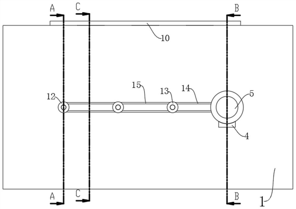
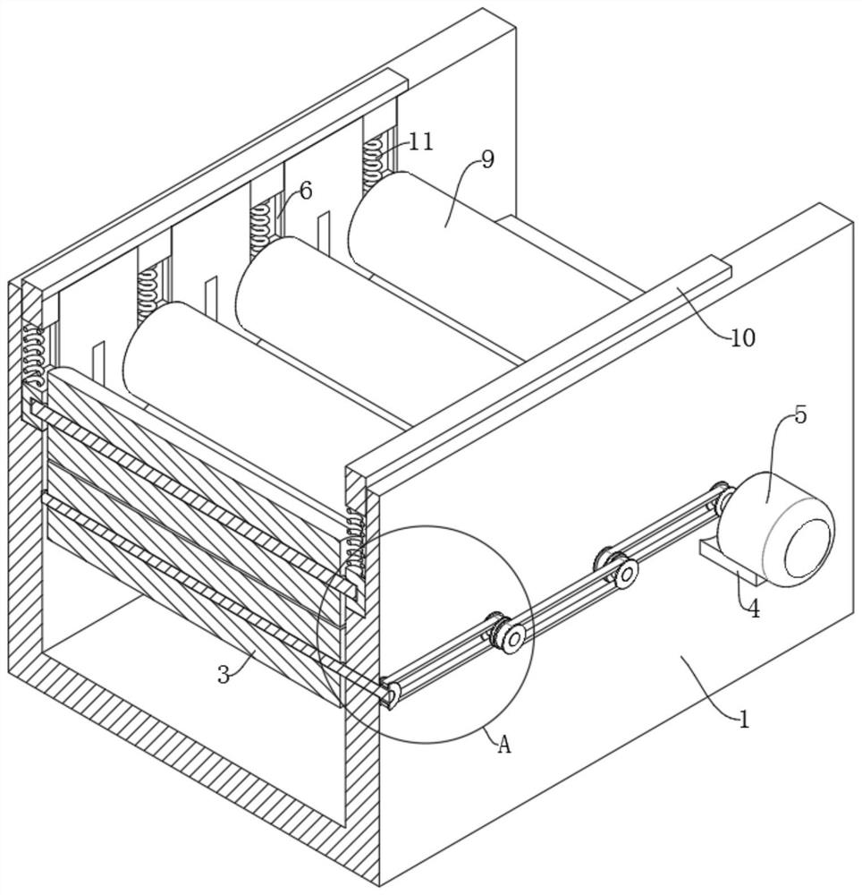
[0025] refer to Figure 1-7 , a tension leveling machine for washing machine drum preparation, comprising a support seat 1, a plurality of first rotating shafts 2 are placed on one side of the bearing seat 1, the plurality of first rotating shafts 2 is set to four, and the plurality of first rotating shafts 2 are each Through the bearing through the support base 1, the first rolling rollers 3 are installed on the multiple first rotating shafts 2 inside the support base 1, the multiple first rolling rollers 3 are set to four, and the motor base 4 is installed on one side of the support base 1 , a motor 5 is installed on the motor base 4 (the end of the support base 1 close to the motor 5 is the feed port), the output shaft of the motor 5 is connected with one of the first rotating shafts 2, and a plurality of first rotating shafts 2 are connected by a transmission mechanism. Connection; base 1 bottom is provided with a plurality of chute 6, and a plurality of chute 6 is set to ...

Embodiment 2

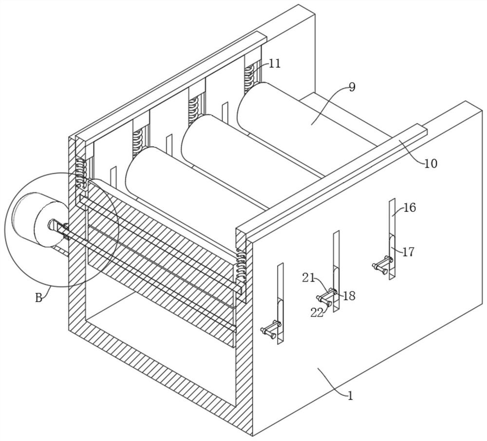
[0028] refer to Figure 1-7 The supporting seat 1 is provided with three grooves 16 on the side away from the motor 5, and the three grooves 16 are arranged at intervals, and a partition 17 is slidably arranged in the three grooves 16, and the supporting seat 1 is close to the three grooves 16- The third rotating shaft 18 is placed on each side, and the three third rotating shafts 18 all pass through the support seat 1 through bearings and are equipped with two gears 19. The two gears 19 on the third rotating shaft 18 are arranged at intervals, and three partitions 17 is equipped with a rack 20 near the side of the gear 19, and a plurality of racks 20 are meshed with a plurality of gears 19, and the three third rotating shafts 18 on the outside of the support base 1 are equipped with connecting blocks 21, three There are pins 22 placed on the side of the connecting block 21 away from the support base 1, and the three pins 22 are threaded through the connecting block 21 and abu...


PUM


Abstract

The invention relates to the technical field of withdrawal and straightening machines, in particular to a withdrawal and straightening machine for washing machine drum manufacturing. The withdrawal and straightening machine comprises a supporting seat; a plurality of first rotating shafts are placed at one side of a bearing seat; the plurality of first rotating shafts each penetrate through the supporting seat through a bearing; a motor seat is mounted at one side of the supporting seat; a motor is mounted on the motor seat; an output shaft of the motor is connected with one of the first rotating shafts; the plurality of first rotating shafts are connected through a transmission mechanism; a plurality of sliding grooves are formed in the bottom part of the base; the plurality of sliding grooves are arranged at intervals; a sliding block is arranged in each sliding groove in a sliding manner; a second rotating shaft is installed between two corresponding sliding blocks; a second rolling roller is installed at the outer sides of each second rotating shaft; a sealing cover is installed on the grooves in each of the two sides of the top part of the supporting base; and the two sealing covers are connected with the multiple sliding blocks through springs. The withdrawal and straightening machine has very high practical value, and is worthy of being popularized.

Description

technical field [0001] The invention relates to the technical field of tension leveling machines, in particular to a tension leveling machine used for preparing washing machine drums. Background technique [0002] With the development of science and technology, people's lives have undergone earth-shaking changes, and washing machines are almost necessary for every household. The main components in a washing machine include a motor, a controller, a drum, a casing, and a cover. The drum of the washing machine is mainly made of stainless steel iron sheet. During the preparation process, the iron sheet needs to be leveled before it can be bent into a barrel. However, due to the different specifications of the washing machine, the iron sheet of the washing machine drum is leveled in the tension leveling machine. It is cumbersome, and it takes too long to level the iron sheet of the washing machine inner cylinder. Contents of the invention [0003] The purpose of the present i...

Claims


Application Information

Patent Timeline
IPC IPC(8): B21D1/02
CPCB21D1/02
Inventor 徐静静
Owner 浙江宏泰精密科技有限公司
Why Eureka
Try Eureka