Residue separation device for municipal sewage treatment
A technology of municipal sewage and separation device, which is applied in the feeding/discharging device of sedimentation tank, filtration separation, sedimentation separation and other directions, which can solve the problem of inability to clean the inside of the device.
- Summary
- Abstract
- Description
- Claims
- Application Information
AI Technical Summary
Problems solved by technology
Method used
Image

Examples
Embodiment 1
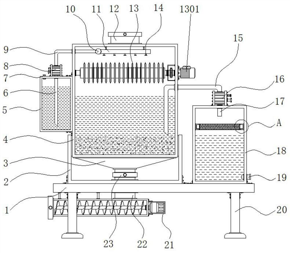
[0027] Example 1: See Figure 1-4 , a residue separation device for municipal sewage treatment, comprising a bottom plate 1, the four corners of the bottom end of the bottom plate 1 are respectively fixedly connected with supporting feet 20, the top of the bottom plate 1 is fixedly connected with a fixed groove 2, and the top of the fixed groove 2 is The housing 4 is fixedly connected, the middle position of the top end of the housing 4 is fixedly connected with the feeding port 12, the bottom end of the housing 4 is fixedly connected with the lower hopper 3, and the middle position of the bottom end of the lower hopper 3 is fixedly connected with the feeding pipe 22. A control valve 23 is provided at the top of the feeding pipe 22, and the bottom of the feeding pipe 22 runs through the middle of the bottom of the fixing groove 2 and the top side of the bottom plate 1, and between the two sides of the housing 4. A crushing mechanism 13 is arranged on the top, and a filter box ...
Embodiment 2
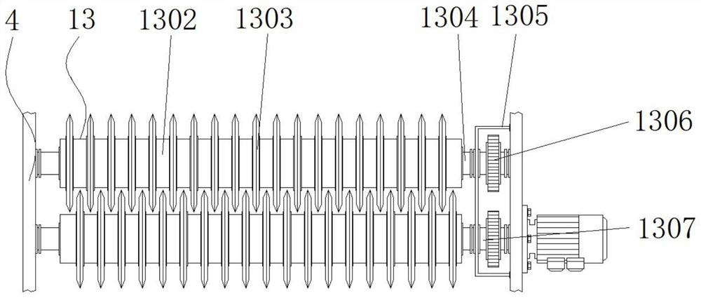
[0032] Embodiment 2: The crushing mechanism 13 is composed of a first drive motor 1301, a fixed cylinder 1302, a crushing tool 1303, a first drive shaft 1304, a protective shell 1305, a linkage gear 1306 and a second drive shaft 1307, and the first drive motor 1301 is fixedly connected At the front end of the top on the other side of the housing 4, the model of the first drive motor 1301 can be Y90S-2, and the first drive shaft 1304 is movably connected to the front end of the top between the two sides inside the housing 4. The first drive shaft 1304 One side of one side runs through the top of one side of the interior of the housing 4 and is fixedly connected to the output end of the first drive motor 1301, and the second drive shaft 1307 is movably connected to the rear end of the top between the two sides of the interior of the housing 4, and the first drive shaft 1304 Linkage gear 1306 is respectively fixedly connected with the second drive shaft 1307 external side, and the...
Embodiment 3
[0036] Embodiment 3: The discharge mechanism 21 is made up of the second driving motor 2101, the feed cylinder 2102, the conveying shaft 2103 and the discharge port 2104. The feed cylinder 2102 is fixedly connected to one side of the bottom end of the base plate 1, and the top side of the feed cylinder 2102 and The bottom end of the feeding tube 22 is fixedly connected, and one side of the feeding cylinder 2102 is fixedly connected with a second driving motor 2101. The model of the second driving motor 2101 can be Y90L-2, and the inside of the feeding cylinder 2102 is provided with a conveying shaft 2103. One side of the conveying shaft 2103 runs through the middle position of the inner side of the feeding cylinder 2102 and is fixedly connected to the output end of the second driving motor 2101, and the other side of the feeding cylinder 2102 is fixedly connected to a discharge port 2104;
[0037] Specifically, such as figure 1 and Figure 4 As shown, the separated solid dirt...
PUM
 Abstract
Description
Claims
Application Information
 - R&D
- Intellectual Property
- Life Sciences
- Materials
- Tech Scout
- Unparalleled Data Quality
- Higher Quality Content
- 60% Fewer Hallucinations
Browse by: Latest US Patents, China's latest patents, Technical Efficacy Thesaurus, Application Domain, Technology Topic, Popular Technical Reports.
© 2025 PatSnap. All rights reserved.Legal|Privacy policy|Modern Slavery Act Transparency Statement|Sitemap|About US| Contact US: help@patsnap.com