
A cam type focal plane image motion compensation device for space camera

A technology of image motion compensation and space camera, applied in the field of space optical remote sensing, can solve the problems of complex optical image motion system and algorithm, high cost of CCD image sensor, and inability to use electronic image motion compensation, etc., achieving low cost and easy implementation , Easy to adjust the effect

Active Publication Date: 2022-02-15
CHANGGUANG SATELLITE TECH CO LTD
View PDF7 Cites 0 Cited by
  • Summary
  • Abstract
  • Description
  • Claims
  • Application Information

AI Technical Summary

Problems solved by technology

The image-based image motion compensation method establishes a mathematical model that causes image degradation through mathematical methods, and restores the image through a certain algorithm. The calculation is large and the real-time performance is not good. It is mainly used in the post-restoration processing and restoration of the image.
The electronic image motion compensation method is mainly carried out for CCD image sensors, that is, the compensation method that uses charge transfer drive technology to control the CCD exposure to synchronize the image motion speed. The electronic image motion compensation method is limited by the type of image sensor and has electronic image motion The high cost of compensated CCD image sensors
Conventional CMOS image sensors, Bayer format color CCD image sensors, etc. cannot use electronic image motion compensation
The optical image motion compensation method mainly compensates the image motion by rotating the objective lens or the mirror in front of the focal plane. The optical image motion system and algorithm are complicated, the control is difficult and the accuracy is not easy to guarantee

Method used


Image

  • A cam type focal plane image motion compensation device for space camera
  • A cam type focal plane image motion compensation device for space camera
  • A cam type focal plane image motion compensation device for space camera

Examples


Embodiment Construction

[0027] The technical solutions in the embodiments of the present invention will be clearly and completely described below in conjunction with the drawings in the embodiments of the present invention.

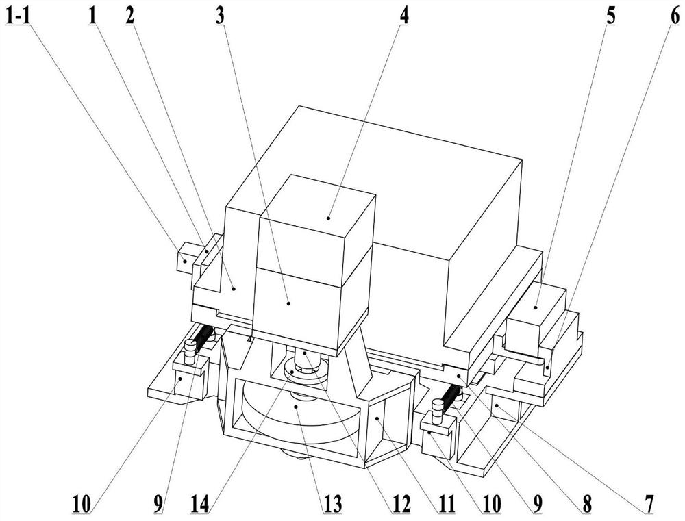
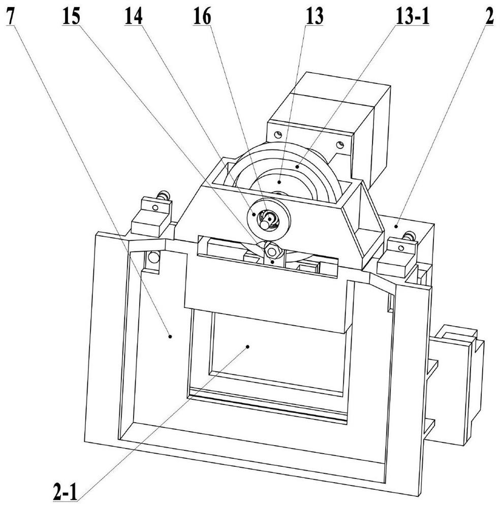
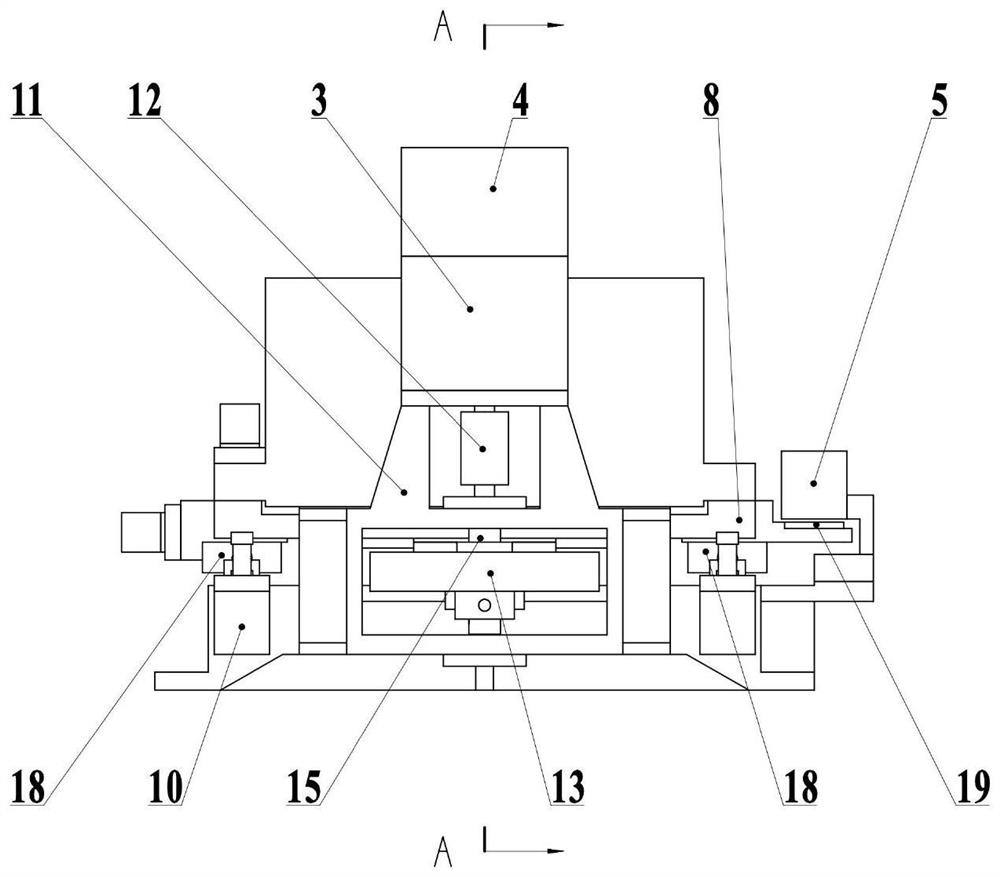
[0028] see Figure 1-8 Describe this embodiment, a cam-type focal plane image motion compensation device for a space camera, which includes a focal plane electric box 2, a stepping motor 3, a fixed frame 7, a moving frame 8, a spring 9, a spring bracket 10, a disc shaped cam 13, cam roller 17 and linear guide rail 18, the movable frame 8 is connected with the fixed frame 7 through two linear guide rails 18 arranged in parallel, the movable frame 8 moves along the linear guide rail 18, and the number of the spring support 10 There are two, two spring brackets 10 are installed on the fixed frame 7, and the two ends of the spring 9 are connected with the spring bracket 10 and the mobile frame 8 respectively, and the focal plane electric box 2 is installed on the mobile frame 8, and...


PUM


Abstract

The invention provides a cam-type focal plane image motion compensation device for a space camera, which belongs to the field of space optical remote sensing. It solves the problem that electronic image motion compensation cannot be used in conventional CMOS image sensors and Bayer format color CCD image sensors. It includes that the mobile frame is connected to the fixed frame through two parallel linear guide rails, the number of spring supports is two, and the two ends of the springs are respectively connected with the spring supports and the mobile frame. The image sensor is installed on the box, the disc cam is installed on the camshaft, the stepper motor and the camshaft are connected through a coupling, the cam roller is fixedly installed in the mounting hole of the cam roller bracket, and the cam roller is located on the disc cam In the groove of the disc cam, the cam profile curve 1 and the cam profile curve 2 of the disc cam are processed according to the image motion compensation motion curve, the camshaft is connected with the disc cam, and the stepping motor drives the disc cam to rotate. It is mainly used for the cam-type focal plane image motion compensation of space cameras.

Description

technical field [0001] The invention belongs to the field of space optical remote sensing, in particular to a cam-type focal plane image motion compensation device for a space camera. Background technique [0002] During the imaging of the space camera, due to the influence of the forward flight of the satellite platform, the image point of the ground object has relative motion on the focal plane. This phenomenon is called forward image motion. The existence of forward image motion will degrade the image formed by the space camera, forming layers of overlapping "smear" phenomenon in the picture, resulting in blurred and distorted images, seriously reducing the resolution of the image, and the resolution directly affects remote sensing. The amount of information that can be obtained in the image and the accuracy of the obtained information, so image motion compensation must be performed to ensure the imaging quality of the space camera. [0003] Currently, image motion compe...

Claims


Application Information

Patent Timeline
Patent Type & Authority Patents(China)
IPC IPC(8): H04N5/225H04N5/232H04N5/372H04N5/374
CPCH04N23/50H04N23/685H04N25/71H04N25/76
Inventor 张弘治李季贾学志张雷刘鸣鹿
Owner CHANGGUANG SATELLITE TECH CO LTD
Learn More