A monitoring system installation device and installation method with short time consumption

A monitoring system and installation device technology, applied in closed-circuit television systems, parts of television systems, parts of color TVs, etc., can solve the problem of speeding up the installation work efficiency of LED lights, shortening installation operation time, installation time and complicated procedures, etc. problem, to achieve the effect of ensuring the photoelectric conversion efficiency

Active Publication Date: 2022-06-07
招商新智科技有限公司
View PDF15 Cites 0 Cited by
  • Summary
  • Abstract
  • Description
  • Claims
  • Application Information

AI Technical Summary

Problems solved by technology

[0004] 1. The comparative document CN109855055A discloses a gravity-based stable LED lamp installation device, "including a telescopic rod, a telescopic rod sleeve, a non-slip sleeve, a holder connection seat, and a light bulb fixing structure. Combined with the bulb converter, when the LED bulb is picked and installed, the operator tilts the hand-held installation device, and the bulb fixing claw is kept vertical to the ground, the operator can quickly align the bulb on the bulb fixing claw with the lamp holder, It avoids the need for staff to stand vertically holding the installation device under the lamp holder to operate, and to look up to observe the installation position of the lamp holder, which reduces neck fatigue caused by LED lamp installation, speeds up the alignment, and avoids problems caused by long-term hand-holding. Arm soreness and shaking caused bulb collision damage; at the same time, through the bulb converter, the old bulb can be removed and the new LED bulb can be installed directly, which shortens the installation operation time and speeds up the work efficiency of LED lamp installation, but the device is integrated. Due to the design, it is impossible to selectively disassemble the device according to the change of the working environment, which makes the installation time and process of the device complicated;
[0005] 2. The comparative document CN109617509A discloses a phase change heat storage solar photovoltaic photothermal flat panel collector, "the invention discloses a phase change thermal storage solar photovoltaic photothermal flat panel collector, which includes a collector shell, installed In the thermal insulation layer in the collector shell, the PCM phase change heat storage plate array installed on the top surface of the thermal insulation layer, the collector plate core flow channel tube installed on the top surface of the PCM phase change thermal storage plate array, installed The packaged photovoltaic cells on the top surface of the collector plate core flow channel tube are installed on the transparent cover plate on the top surface of the packaged photovoltaic cells, and the transparent cover plate is installed at the opening on the top of the collector shell and will collect Heater plate core runner pipe, insulation layer, PCM phase change heat storage plate array and packaged photovoltaic cells are enclosed in the cavity of the collector shell, and the PCM phase change heat storage plate array includes the first phase change heat storage plate Array and the second phase-change heat storage plate array, the first phase-change heat storage plate array completes the absorption of heat from the heat-absorbing plate during the day to achieve the effect of improving battery efficiency; the second phase-change heat storage plate array releases heat at night heat, to achieve the function of preventing the collector from freezing", but there is no structure to effectively change the deflection angle of the photoelectric conversion device, which leads to the limitation of the effective illumination time of the device and the low photoelectric conversion efficiency of the device;
The present invention provides an installation device and installation method of an air gap lightning arrester, which has high installation efficiency, but the device lacks a corresponding positioning device during installation, resulting in the inability to fix the device and adjust the installation height during installation.

Method used


Image

  • A monitoring system installation device and installation method with short time consumption
  • A monitoring system installation device and installation method with short time consumption
  • A monitoring system installation device and installation method with short time consumption

Examples


Embodiment Construction

[0038] The technical solutions in the embodiments of the present invention will be clearly and completely described below with reference to the accompanying drawings in the embodiments of the present invention. Obviously, the described embodiments are only a part of the embodiments of the present invention, but not all of the embodiments. Based on the embodiments of the present invention, all other embodiments obtained by those of ordinary skill in the art without creative efforts shall fall within the protection scope of the present invention.

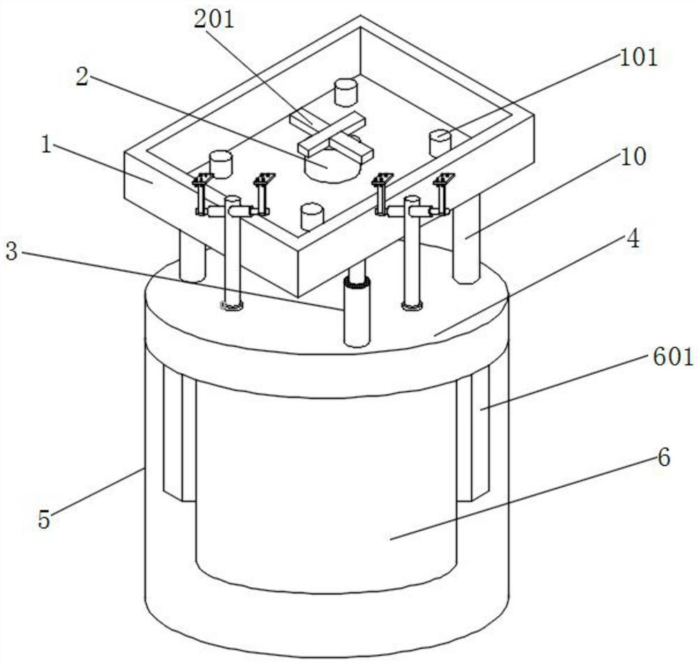
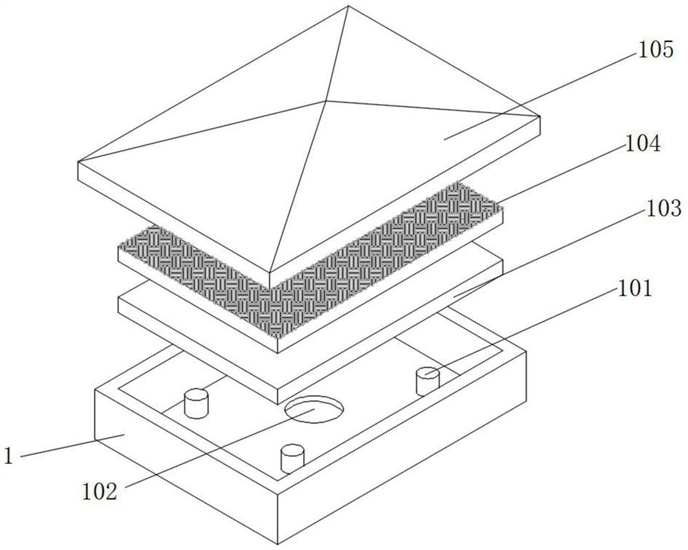
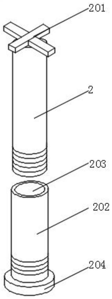
[0039] see Figure 1-Figure 10 , an embodiment provided by the present invention: a short time-consuming monitoring system installation device and installation method, including a photovoltaic cell box 1, a connecting rod 2, a telescopic rod 3, an installation cover 5 and a fitting positioning plate 8, the installation cover 5 is a hollow cylindrical structure, and the hollow mounting cover 5 can provide space for the installation of ...


PUM


Abstract

The invention discloses a time-consuming monitoring system installation device and installation method, which include a photovoltaic battery box, a connecting rod, a telescopic rod and a fitting positioning plate, a disk is fixed on the top of the installation cover, and a disk is fixed on the top of the disk A split rod is installed inside, and a hole is provided inside the split rod, and a solid connecting rod is installed inside the photovoltaic battery box through the No. 1 threaded hole, and a top plate is fixed on the inner wall of the installation cover. The bottom of the top plate is welded with an embedded positioning plate, and a protective cover is slidably installed inside the embedded positioning plate. Two sets of electric sliding bars and long rods are installed at the bottom of the photovoltaic cell box. The bottom slide is connected with a telescopic rod. In the present invention, a connecting rod is provided, which runs through the inside of the photovoltaic cell box and is threadedly connected with the splitting rod extending above the disk, so that the auxiliary device realizes the flexible disassembly and installation of the photovoltaic cell box and the telescopic rod, and shortens the length of the device. The combined installation time of .

Description

technical field [0001] The invention relates to the technical field of monitoring installation devices, in particular to a monitoring system installation device and an installation method with short time consumption. Background technique [0002] The monitoring device can perform all-weather camera monitoring operations in the effective monitoring area. According to the different terrain of the monitoring area, the monitoring device is sometimes installed in the exposed outdoor, and sometimes installed in the interior of the building. The exposed outdoor usually has more abundant sunlight. The light energy of solar radiation can be converted into electrical energy through photoelectric conversion, which can provide working power for monitoring devices and reduce monitoring costs. However, the internal light of buildings is blocked, and the photoelectric conversion structure is difficult to work. However, in order to facilitate installation, monitoring devices usually use The...

Claims


Application Information

Patent Timeline
Patent Type & Authority Patents(China)
IPC IPC(8): H02S20/32H04N5/225H04N5/232H04N7/18
CPCH02S20/32H04N7/18H04N23/51H04N23/55H04N23/695Y02E10/50
Inventor 谢九玲
Owner 招商新智科技有限公司
Why Eureka
Try Eureka