Textile airing device
A drying device and a technology for placing rods, which are applied in the direction of textiles and papermaking, fabric surface trimming, and drying gas arrangement, etc., which can solve the problems that the surface of textiles cannot be flattened, the structure is single, and textile materials cannot be evenly dried.
- Summary
- Abstract
- Description
- Claims
- Application Information
AI Technical Summary
Problems solved by technology
Method used
Image

Examples
Embodiment 1
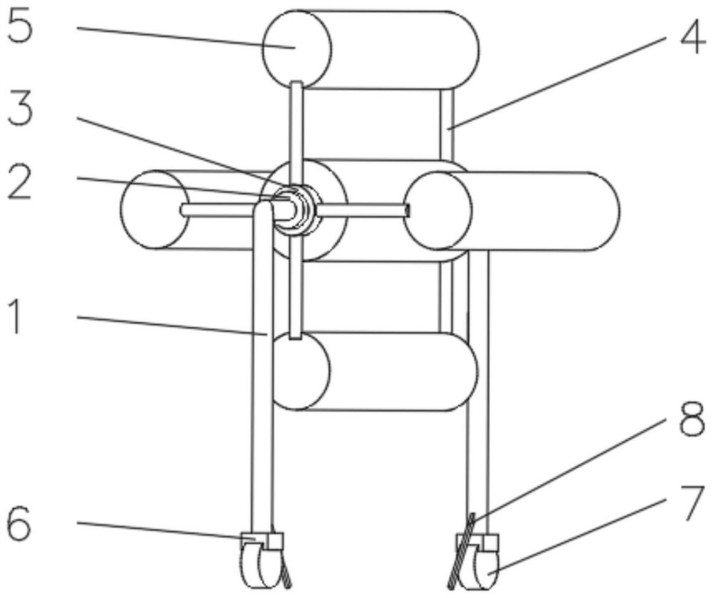
[0031] see Figure 1-3 , the present invention provides a technical solution: a textile drying device, comprising a support frame 1, one end of the support frame 1 is fixedly connected with a support rod 2, the outside of the support rod 2 is provided with a sliding bearing 3, and the outside of the sliding bearing 3 is uniform A connecting rod 4 is installed, and one end of the connecting rod 4 away from the sliding bearing 3 is fixedly connected with a placement rod 5 , and an arc-shaped top plate 9 is installed on one side of the placement rod 5 .
[0032] The end of the support frame 1 away from the support rod 2 is symmetrically installed with a roller bracket 6, the side of the roller bracket 6 away from the support frame 1 is equipped with a universal wheel 7, and the side of the support frame 1 close to the position of the roller bracket 6 is symmetrically installed with a telescopic column 8.
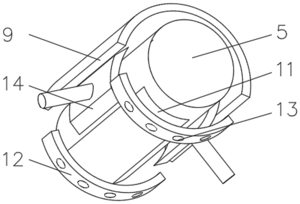
[0033] The first magnet block 11 is installed on the side away from the a...
Embodiment 2
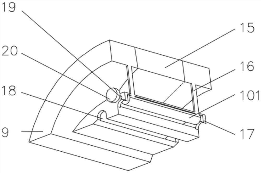
[0039] see Figure 1-4 , the present invention provides a technical solution: on the basis of Embodiment 1, a leveling device 10 is installed on the side of the arc-shaped top plate 9 close to the placement rod 5, and the leveling device 10 includes a round frame 101, and one side of the round frame 101 is connected to the device frame 17 rotation connection, the inside of the circular frame 101 is evenly installed with a limit block 102, one side of the limit block 102 is installed with an elastic rod 103, and the end of the elastic rod 103 away from the limit block 102 is fixedly connected with a flat arc plate 104, the limit block A connecting block 105 is fixedly connected to the side of the 102 away from the round frame 101 , and a fixed rod 106 is fixedly connected to the side of the connecting block 105 away from the limiting block 102 .
[0040] One side of the round frame 101 is fixedly connected with a rotating rod 19 , the end of the rotating rod 19 away from the ro...
Embodiment 3
[0043] see Figure 1-5 , the present invention provides a technical solution: on the basis of Embodiment 2, a drying device 14 is installed on one side of the rod 5 close to the arc-shaped top plate 9, the drying device 14 includes a shell 141, and the inner wall of the shell 141 is symmetrical A fixed bracket 142 is installed, and a heating wire 143 is installed on the side of the fixed bracket 142 away from the casing 141. A drying motor 144 is installed on the inner bottom of the casing 141, and the output end of the drying motor 144 is rotatably connected with a rotating column 145. The rotating column 145 One end of the housing 141 is fixedly connected with a fan blade 146 , one side of the casing 141 is connected with a top frame 147 , and an elastic plate 148 is connected with the inner wall of the top frame 147 .
[0044] When in use, turn on the drying motor 144 to drive the fan blade 146 to rotate, so that the air inside the casing 141 is blown to the top frame 147 t...
PUM
 Abstract
Description
Claims
Application Information
 - Generate Ideas
- Intellectual Property
- Life Sciences
- Materials
- Tech Scout
- Unparalleled Data Quality
- Higher Quality Content
- 60% Fewer Hallucinations
Browse by: Latest US Patents, China's latest patents, Technical Efficacy Thesaurus, Application Domain, Technology Topic, Popular Technical Reports.
© 2025 PatSnap. All rights reserved.Legal|Privacy policy|Modern Slavery Act Transparency Statement|Sitemap|About US| Contact US: help@patsnap.com