
Robot gripper and control method thereof

A robot gripper and control part technology, applied in the field of robotics, can solve the problems of inability to limit the gripper, poor integration, and failure to provide, etc., and achieve the effects of improved integration, compact structure, and small size

Pending Publication Date: 2021-05-07
TSINGHUA UNIV +1
View PDF0 Cites 2 Cited by
  • Summary
  • Abstract
  • Description
  • Claims
  • Application Information

AI Technical Summary

Problems solved by technology

[0002] In the field of robotics, the robot gripper is installed at the end of the robot to realize the terminal effector for the robot to grab objects. The fully-driven robot gripper usually installs a driver for each joint component. The device is cumbersome and complicated, and the overall gripper is bulky and poorly integrated.
The underactuated robot gripper, although the number of actuators is reduced, cannot precisely control the gripper's clamping force
[0003] Although the existing robot grippers can grasp the objects with the gripper, it often requires a large output power of the motor to move the fingers of the gripper to a suitable position and have a certain clamping force
[0004] Moreover, the existing robot gripper cannot provide real-time grasping information to the robot body or the operator's operation terminal, and the operator cannot limit the movement of the gripper according to the real-time grasping situation. The robot provides more information to improve the robot's grasping ability is the key to improving the robot's intelligent characteristics

Method used


Image

  • Robot gripper and control method thereof
  • Robot gripper and control method thereof
  • Robot gripper and control method thereof

Examples


Embodiment Construction

[0038] In order to make the object, technical scheme and advantages of the present invention clearer, a specific embodiment in the present invention will be clearly and completely described below in conjunction with the accompanying drawings. Obviously, the described specific embodiment is an example of implementing the present invention , does not constitute a limitation to the scope of the present invention. Based on the implementation manners in the present invention, all other implementation manners obtained by persons of ordinary skill in the art without creative efforts fall within the protection scope of the present invention.

[0039] In addition, the term "and / or" in this article is only an association relationship describing associated objects, which means that there may be three relationships, for example, A and / or B, which may mean: A exists alone, A and B exist at the same time, There are three cases of B alone. In addition, the character " / " in this article gene...


PUM


Abstract

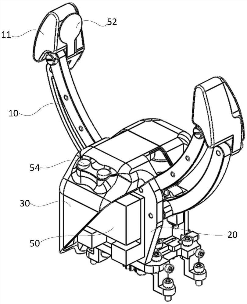
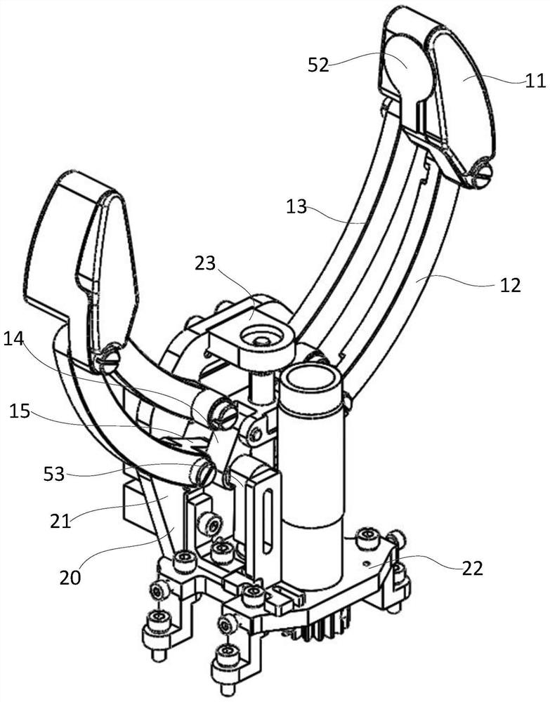
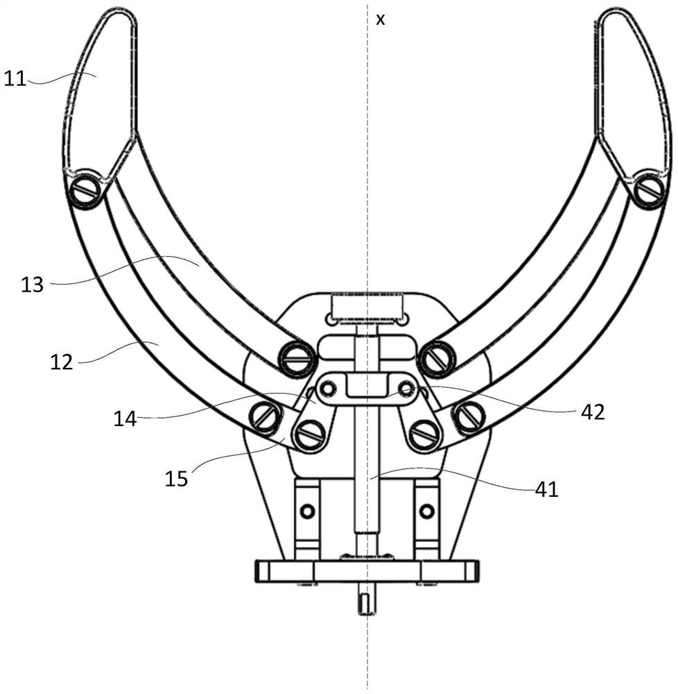
The invention provides a robot gripper and a control method thereof. The gripper comprises a support and a plurality of gripper mechanisms arranged on the support, each gripper mechanism comprises a fingertip part, a first connecting rod and a second connecting rod, each fingertip part swings around the support under the support of the first connecting rod and the second connecting rod and swings towards the center shaft side of the support to be folded, in the folded state, the first connecting rod is located on the outer side of a center shaft of the support, the second connecting rod is located on the inner side of the center shaft of the support, a lead screw for driving is arranged along the center shaft of the support, the lead screw is sleeved with a lead screw nut, a push rod is arranged for each gripper mechanism, one end of each push rod is rotationally connected with the lead screw nut, and the other ends of the push rods are rotatably connected with swing arms extending from the other end of the first connecting rod or the second connecting rod to the opposite side of the body part of the first connecting rod or the second connecting rod. The robot gripper is small in size and compact in structure. Real-time communication with the robot gripper is realized through the Ethercat.

Description

technical field [0001] The present invention generally relates to the field of robotics, and more particularly, to a robot gripper and a control method thereof. Background technique [0002] In the field of robotics, the robot gripper is installed at the end of the robot to realize the terminal effector for the robot to grab objects. The fully-driven robot gripper usually installs a driver for each joint component. The device is cumbersome and complicated, and the overall gripper is bulky and poorly integrated. The underactuated robotic gripper, although the number of actuators is reduced, cannot precisely control the gripper's clamping force. [0003] Although the existing robot grippers can realize the gripping of objects by the grippers, it often requires a large power output by the motor to move the fingers of the grippers to a suitable position and have a certain clamping force. [0004] Moreover, the existing robot gripper cannot provide real-time grasping information...

Claims


Application Information

Patent Timeline
IPC IPC(8): B25J15/02B25J13/00B25J13/08B25J15/08B25J19/02
CPCB25J15/0213B25J15/08B25J13/084B25J13/088B25J19/023B25J13/006
Inventor 刘辛军李鹏韩广超谢福贵叶彦雷李子豪吕春哲刘魁
Owner TSINGHUA UNIV
Learn More