
PET-CT scanning system and method

A PET-CT and scanning system technology, applied in PET-CT scanning systems and fields, can solve the problems of expensive equipment, immobility, and no energy storage modules, and achieve the effects of low cost, strong pertinence, and convenient transfer and use

Pending Publication Date: 2021-05-07
FMI MEDICAL SYST CO LTD
View PDF8 Cites 0 Cited by
  • Summary
  • Abstract
  • Description
  • Claims
  • Application Information

AI Technical Summary

Problems solved by technology

[0002] Existing PET / CT equipment is mainly PET / CT for whole-body diagnosis. The PET / CT machine mainly includes two parts: a rack and a diagnostic bed. The rack is composed of a CT rack and a PET rack, which are used for CT Scanning and PET scanning, but the volume is large and the equipment is expensive; and there is no energy storage module, and it needs to be powered by an external power supply all the time; it cannot be moved, has no self-shielding, and needs to be equipped with its own diagnostic bed to scan, and cannot enter the operation Scanning in places such as rooms or wards

Method used


Image

  • PET-CT scanning system and method
  • PET-CT scanning system and method
  • PET-CT scanning system and method

Examples


Embodiment Construction

[0031] The advantages of the present invention will be further elaborated below in conjunction with the accompanying drawings and specific embodiments.

[0032] Reference will now be made in detail to the exemplary embodiments, examples of which are illustrated in the accompanying drawings. When the following description refers to the accompanying drawings, the same numerals in different drawings refer to the same or similar elements unless otherwise indicated. The implementations described in the following exemplary examples do not represent all implementations consistent with the present disclosure. Rather, they are merely examples of apparatuses and methods consistent with aspects of the present disclosure as recited in the appended claims.

[0033] The terminology used in the present disclosure is for the purpose of describing particular embodiments only, and is not intended to limit the present disclosure. As used in this disclosure and the appended claims, the singular...


PUM


Abstract

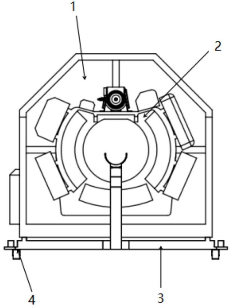
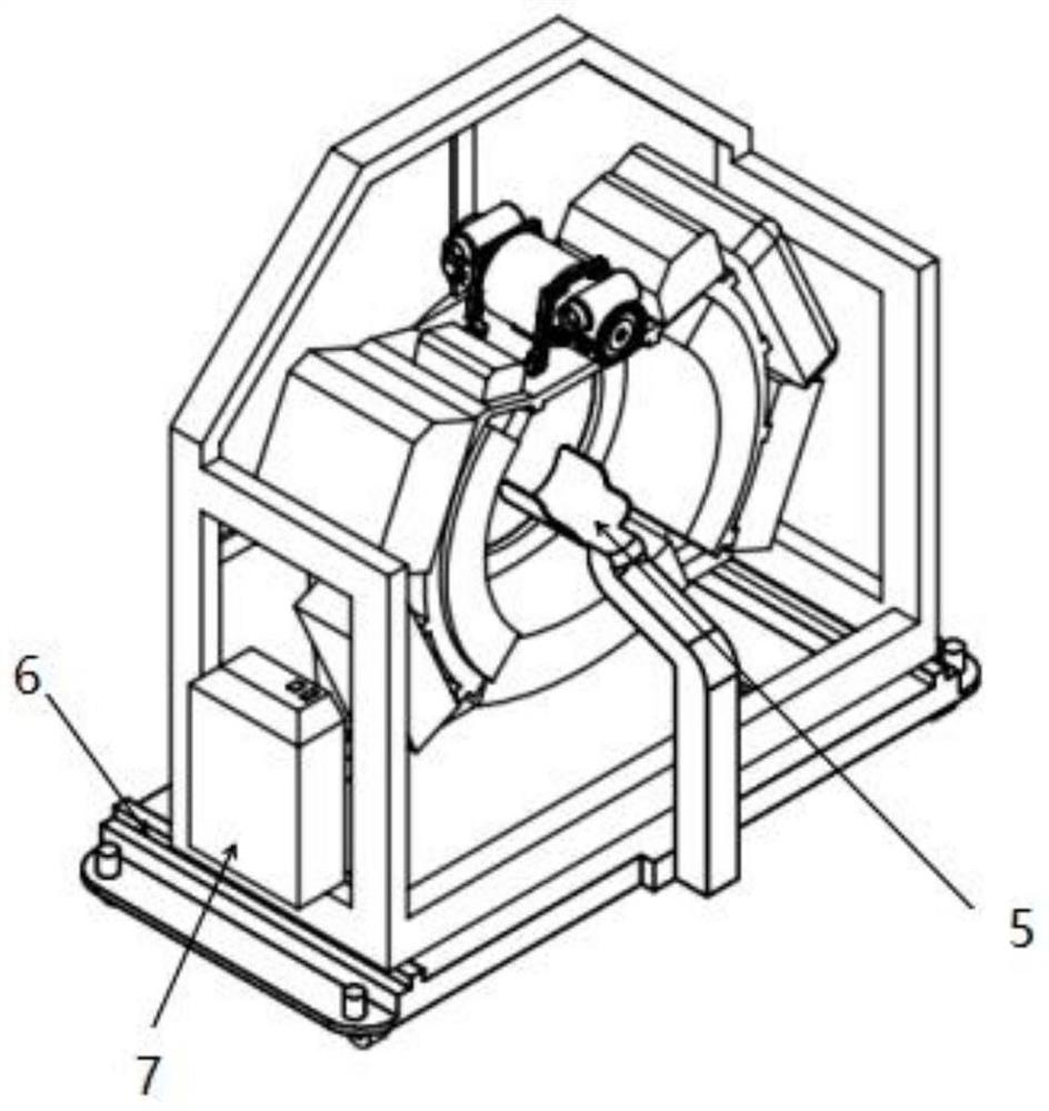
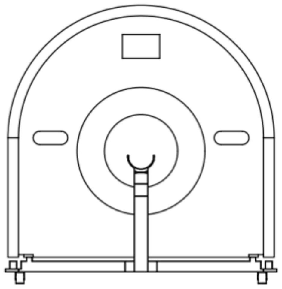
The invention discloses a PET-CT scanning system and method. The PET-CT scanning system comprises a base, an annular scanning frame movably arranged on the base and a bracket fixedly arranged on the base, and a scanned part is arranged on the bracket; a CT scanning assembly and a PET scanning assembly are arranged on the annular scanning frame, and the CT scanning assembly and the PET scanning assembly rotate in the circumferential direction to change the scanning direction; and the annular scanning frame axially moves relative to the base, so that the scanned part on the bracket is arranged in the scanning range of the CT scanning assembly / PET scanning assembly or is not arranged in the scanning range of the CT scanning assembly / PET scanning assembly. The CT scanning assembly and the PET scanning assembly are integrated on the annular scanning frame at the same time, and compared with two scanning frames in the prior art, the PET-CT scanning system is low in cost; and only the annular scanning frame is arranged, so that the structure is small, and the PET-CT scanning system can be conveniently transferred to wards, operating rooms and other spaces for scanning work.

Description

technical field [0001] The present invention relates to the technical field of PET-CT, in particular to a PET-CT scanning system and method. Background technique [0002] Existing PET / CT equipment is mainly PET / CT for whole-body diagnosis. The PET / CT machine mainly includes two parts: a rack and a diagnostic bed. The rack is composed of a CT rack and a PET rack, which are used for CT Scanning and PET scanning, but the volume is large and the equipment is expensive; there is no energy storage module, and it needs to be powered by an external power supply all the time; it cannot be moved, has no self-shielding, and needs to be equipped with its own diagnostic bed to scan, and cannot enter the operation Scanning in places such as rooms or wards. Contents of the invention [0003] In order to overcome the above-mentioned technical defects, the object of the present invention is to provide a movable PET-CT scanning system and method for local parts. [0004] The invention dis...

Claims


Application Information

Patent Timeline
Patent Type & Authority Applications(China)
IPC IPC(8): A61B6/03
CPCA61B6/032A61B6/035A61B6/037A61B6/44A61B6/4435A61B6/501A61B6/5235
Inventor 黄振强金佳超吴杰李雷
Owner FMI MEDICAL SYST CO LTD
Learn More