Sliding bearing

A technology for sliding bearings and shields, which is applied in the direction of sliding contact bearings, bearings, and bearings for rotational motion, etc., can solve the problems of high integration, large additional space, and small size, and achieve high integration and reliability, power generation and The effect of strong power supply capacity and simple overall structure

Active Publication Date: 2021-05-04
ZHEJIANG NORMAL UNIVERSITY
View PDF4 Cites 2 Cited by
  • Summary
  • Abstract
  • Description
  • Claims
  • Application Information

AI Technical Summary

Problems solved by technology

At present, most of the bearings with self-power monitoring function proposed use the electromagnetic principle and the piezoelectric principle to generate electricity. The disadvantages of electromagnetic power generation are the existence of magnetic interference and weak power generation capacity at low speeds. The disadvantages of piezoelectric power generation are that the additional space required is relatively large, Piezoelectric ceramics will depolarize when the temperature is too high
Obviously, the existing technology still has great limitations in practical application, and various bearings with self-powered monitoring functions that are small in size and highly integrated, especially suitable for high-temperature environments, are still urgently needed by various industries.

Method used


Image

  • Sliding bearing
  • Sliding bearing
  • Sliding bearing

Examples


Embodiment Construction

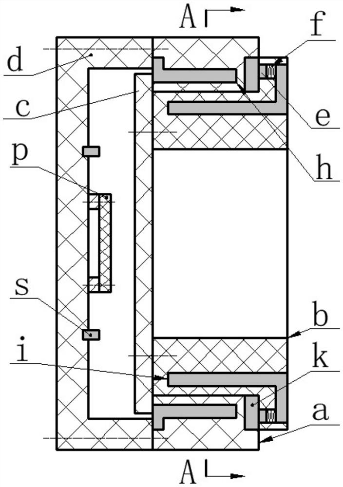
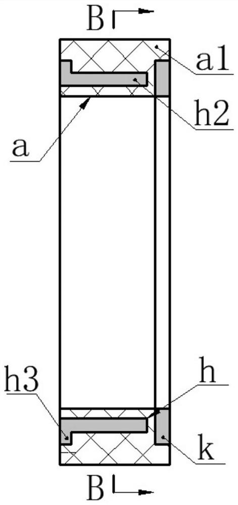
[0022] The present invention proposes a sliding bearing, which mainly includes an outer ring a, an inner ring b, a baffle c, a shield d, a sensor s and a circuit board p, and the circuit board p and the sensor s are installed inside the shield d, and the outer ring a Set on the inner ring b, one end of the inner ring b is provided with a retaining ring b2, the other end is installed with a baffle c through screws, the outer ring a is limited by the baffle c and retaining ring b1, and the shield d is installed on the outer ring through screws the end of a.

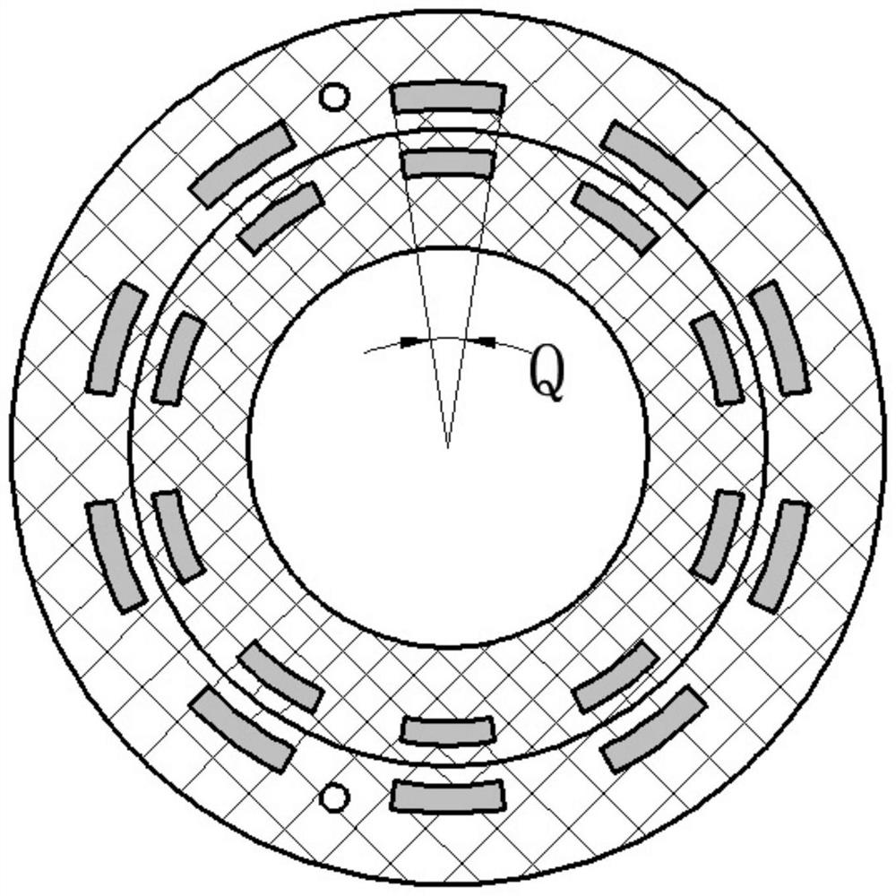
[0023] The outer ring a is composed of the outer ring body a1, the outer electrode h and the electrode ring k, the outer electrode h is composed of the outer pole ring h1, the outer pole finger h2 and the outer terminal h3, and the outer pole fingers h2 are evenly distributed on the right side of the outer pole ring h1 , the outer pole finger h2 is parallel to the axis of the outer pole ring h1, the outer terminal h3 is loc...


PUM


Abstract

The invention relates to a sliding bearing, and belongs to the technical fields of bearing monitoring and new energy. The sliding bearing comprises an inner ring, an outer ring, a baffle, a shield, a sensor and a circuit board, wherein the outer ring is composed of an outer ring body and an outer electrode, the outer electrode is composed of an outer electrode ring, outer electrode fingers and an outer terminal, and the outer electrode fingers are arranged in the outer ring body; the inner ring is composed of an inner ring body and an inner electrode, the inner electrode is composed of an inner electrode ring and inner electrode fingers, the inner electrode fingers are arranged in the inner ring body, and the electrode ring is in sliding contact with the inner electrode ring through a conductive block; the inner electrode fingers and the outer electrode fingers are equal in number and central angle; the inner ring and the outer ring are made of two kinds of high polymer materials with friction electricity sequences far away from each other, inductive charges with different attributes are arranged between contact surfaces in the relative rotation process of the inner ring and the outer ring, and potential difference is generated between the adjacent inner electrode finger and outer electrode finger in the two circumferential directions; and the inner electrode fingers and the outer electrode fingers are alternately overlapped and separated in the circumferential direction, so that the potential difference between the inner electrode and the outer electrode is alternately increased and decreased, mechanical energy is converted into electric energy, and the generated electric energy is supplied to a sensor and an information transmitting system after being treated.

Description

technical field [0001] The invention belongs to the technical field of bearing monitoring and new energy, and in particular relates to a sliding bearing. Background technique [0002] Bearings are indispensable standard parts in the fields of machine tools, transportation tools, mining machinery and light industrial machinery, and are also one of the most vulnerable parts in related transmission systems. 30% of rotating machinery failures are caused by bearing failures. Therefore, bearing condition monitoring and early fault diagnosis have attracted people's attention. On-line monitoring of bearings and their transmission systems has become a prerequisite for reliable operation of related equipment in the fields of generators, ships, high-speed rail, and aircraft. The performance indicators to be monitored include temperature, vibration, speed, and noise. The initial bearing monitoring system is mainly a separate external structure, which belongs to the category of non-cont...

Claims


Application Information

Patent Timeline
Patent Type & Authority Applications(China)
IPC IPC(8): F16C17/12F16C33/20H02N1/04
CPCF16C17/12F16C33/201H02N1/04
Inventor 阚君武王凯张敏陈松汪彬曹红兵曾平程光明
Owner ZHEJIANG NORMAL UNIVERSITY
Why Eureka
Try Eureka