
Crankshaft, rotor type compressor and air conditioner

A technology of rotor compressors, applied in the fields of rotor compressors, crankshafts, and air conditioners, which can solve the problems that compressors cannot meet the requirements of large displacement and miniaturization at the same time, and the installation structure of pistons is limited.

Pending Publication Date: 2021-05-04
GREE ELECTRIC APPLIANCES INC
View PDF0 Cites 0 Cited by
  • Summary
  • Abstract
  • Description
  • Claims
  • Application Information

AI Technical Summary

Problems solved by technology

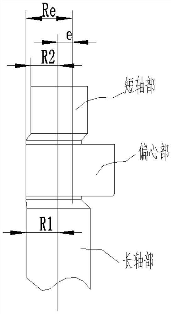
[0005] Therefore, the present invention provides a kind of crankshaft, rotor type compressor, air conditioner, to overcome the eccentricity of crankshaft eccentric part in the prior art is limited by the smaller value in the diameter of long shaft section and the diameter of short shaft section, cause piston The installation structure is limited, and the compressor cannot meet the needs of large displacement and miniaturization design at the same time.

Method used


Image

  • Crankshaft, rotor type compressor and air conditioner
  • Crankshaft, rotor type compressor and air conditioner
  • Crankshaft, rotor type compressor and air conditioner

Examples


Embodiment Construction

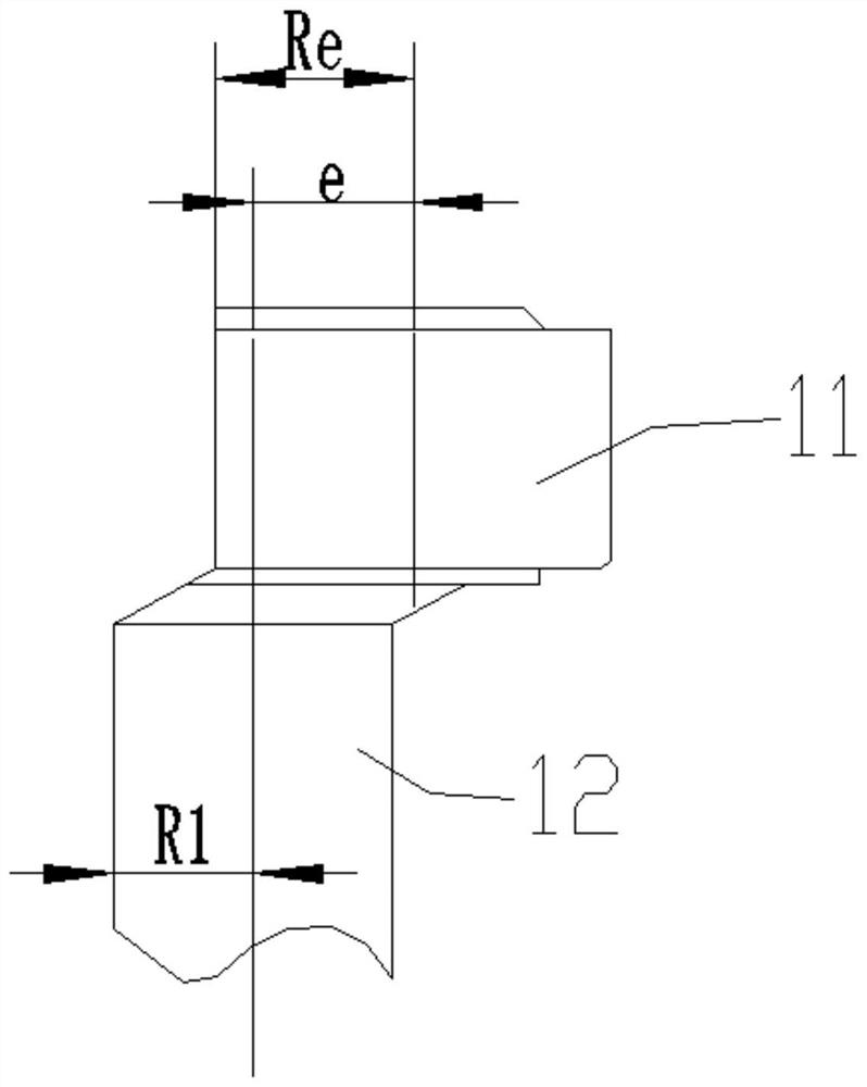
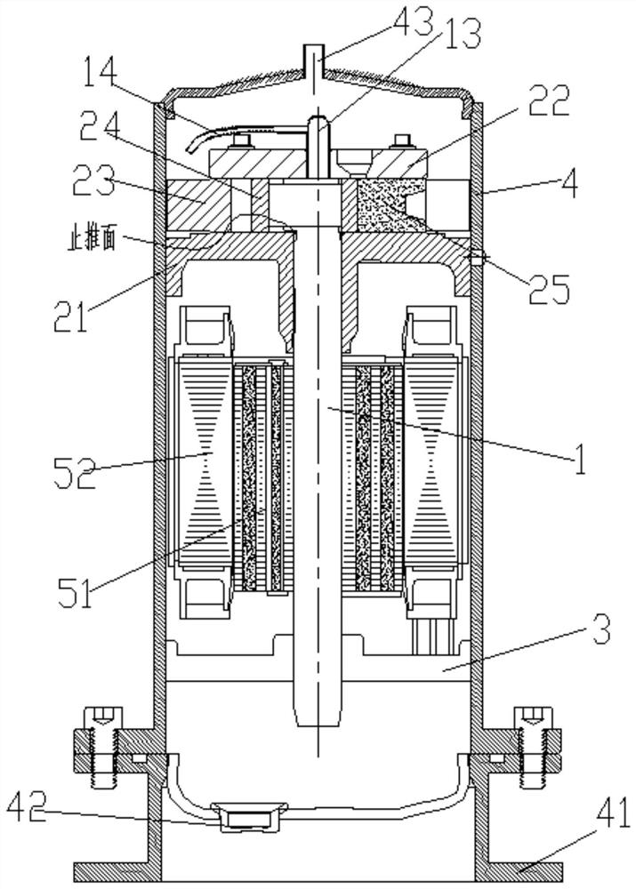
[0028] see in conjunction Figure 1 to Figure 9 As shown, according to an embodiment of the present invention, a crankshaft is provided, including an eccentric portion 11 and a shaft section 12, the shaft section 12 is located on the first end surface of the eccentric portion 11 and the second end surface of the eccentric portion 11 There is no protruding shaft section. In this technical solution, compared with the crankshaft in the prior art, the crankshaft is only provided with the rotating shaft section 12 on one side of the eccentric part 11 so that the crankshaft objectively forms a structure without a short shaft, so The design of the installation structure of the roller 24 (also known as the piston) is no longer limited by the min{R1, R2} conditions in the prior art, and thus can meet the compressor's large displacement requirements while meeting the compressor's requirements. miniaturization design requirements.

[0029] specific, figure 1 Shows the local structure ...


PUM


Abstract

The invention provides a crankshaft, a rotor type compressor and an air conditioner. The crankshaft comprises an eccentric part and a rotating shaft section, wherein the rotating shaft section is located on a first end face of the eccentric part, and no protruding shaft section exists on a second end face of the eccentric part. According to the crankshaft, compared with a crankshaft in the prior art, the crankshaft is only provided with the rotating shaft section on one side of the eccentric part, so that the crankshaft objectively forms a short-shaft-free structure, therefore, the design on the aspect of a mounting structure of a roller is no longer subjected to condition limitation of min {R1, R2} in the prior art, and then the miniaturization design requirement of the compressor can be met while the large displacement requirement of the compressor is met.

Description

technical field [0001] The invention belongs to the technical field of compressor manufacturing, and in particular relates to a crankshaft, a rotor compressor and an air conditioner. Background technique [0002] At present, the motor assembly in the rotary compressor (hereinafter also referred to as the traditional rotary compressor) is arranged above the pump body assembly, so that the exhaust gas of the pump body assembly can be used to cool the motor assembly as necessary, and the pump body assembly is at the same time The oil pool at the bottom of the compressor casing can seal the leakage gap of the pump body assembly, but the crankshaft used has a short shaft section and a long shaft section on both sides of the eccentric part. The crankshaft with this structure has the following disadvantages: [0003] (1) In order to ensure that the piston (roller) can fit on the eccentric part of the crankshaft, it must be satisfied that the difference between the radius Re of the ...

Claims


Application Information

Patent Timeline
Patent Type & Authority Applications(China)
IPC IPC(8): F04C29/00F04C29/02F04C28/24F04C29/04F04C29/12F25B1/04
CPCF04C29/00F04C29/02F04C28/24F04C29/04F04C29/12F25B1/04
Inventor 胡余生魏会军徐嘉赵海红余冰杨欧翔
Owner GREE ELECTRIC APPLIANCES INC
Learn More