
Efficient spraying dust falling device for constructional engineering

A technology for construction engineering and dust suppression devices, which is applied to spray devices, liquid spray devices, buildings, etc., can solve the problems of multi-space, easy formation of dust, and poor dust suppression effect, so as to improve efficiency, facilitate storage and placement, and reduce occupancy. effect of space

Active Publication Date: 2021-05-04
新疆伟业天成建设工程有限公司
View PDF8 Cites 5 Cited by
  • Summary
  • Abstract
  • Description
  • Claims
  • Application Information

AI Technical Summary

Problems solved by technology

[0002] Construction engineering refers to various technical work such as planning, survey, design and construction, completion, etc. for new construction, reconstruction or expansion of housing buildings and their auxiliary facilities, and the completion of project entities and the installation of supporting lines, pipelines, and equipment. Earthwork needs to be excavated during the construction of the project. The construction site is an earthy ground, which is easy to form dust. The dust will affect the construction personnel, construction machinery and surrounding residents. It is necessary to reduce dust on the construction site. The existing sprinkler dust reduction devices are usually only Spray wheel dust reduction treatment can be carried out at a fixed height. Due to the large area and space of the construction site, the fixed spray dust reduction method cannot meet the demand, and the dust reduction effect is poor. Most of the spray dust reduction devices are fixed structures, and their volume is large. It takes up a lot of space and is not convenient for storage

Method used


Image

  • Efficient spraying dust falling device for constructional engineering
  • Efficient spraying dust falling device for constructional engineering
  • Efficient spraying dust falling device for constructional engineering

Examples


Embodiment approach

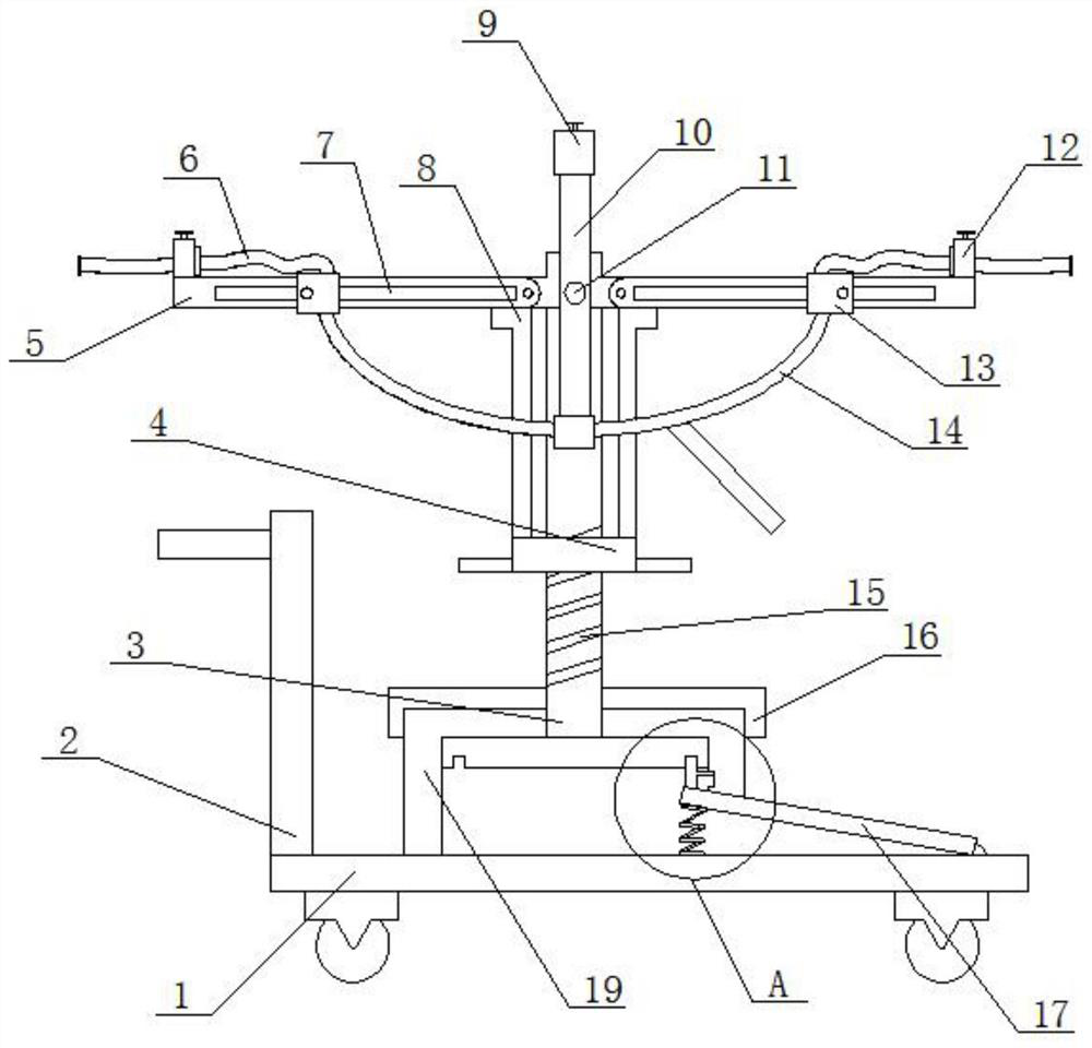
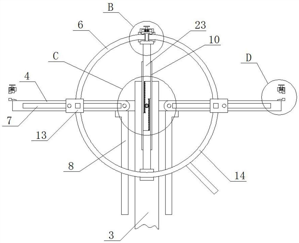
[0032]As a preferred embodiment of the present invention, the top of the inner side of the lower fixed block 12 is movably installed with an L-shaped clamping plate 30, and the top of the L-shaped clamping plate 30 is provided with an operating rod 24, on which the operating rod 25 An operating rod spring 25 is installed to facilitate fixing one end of the upper water pipe 6 and adjust the spraying area of ​​the device.

[0033] As a preferred embodiment of the present invention, the shape of the telescopic plate 23 is "L", which is convenient for the gear 29 to drive the rack 31 to drive the telescopic plate 23 up and down.

[0034] As a preferred embodiment of the present invention, a clamping plate 26 is movably installed inside the upper fixed block 9 on the top, and an operating rod 24 is fixedly installed on the top of the clamping plate 26, and an operating rod is installed on the operating rod 24. The spring 25 can fix one end of the upper water pipe 6 and adjust the s...


PUM


Abstract

The invention provides an efficient spraying dust fall device for constructional engineering. The efficient spraying dust fall device comprises a base, a rotating rod, a movable rod, an upper water pipe, an adjusting frame, a fixed rod, a lower water pipe, a pedal and a storage box, the storage box is fixedly mounted at the top of the base, the pedal is movably mounted on one side of the storage box through a hinge, a pressing spring is fixedly mounted between one end of the pedal and the base, a limiting plate clamping rod is slidably mounted in the interior of a storage box sliding groove, the bottom end of the rotating rod is rotatably mounted at the top of the storage box through a protective cover and a limiting plate, and the protective cover is arranged at the top of the storage box. According to the efficient spraying dust falling device for constructional engineering, adjusting can be conveniently carried out on the spraying angle, the spraying height and the spraying direction, the spraying direction is kept consistent, the spraying and dust falling efficiency is improved, folding can be carried out through the adjusting frame and an adjusting nut, the therefore occupied space of the device is reduced, and storage is convenient.

Description

technical field [0001] The invention relates to the technical field of dust suppression in construction engineering, in particular to a high-efficiency spray dust suppression device for construction engineering. Background technique [0002] Construction engineering refers to various technical work such as planning, surveying, design, construction, and completion for new construction, reconstruction or expansion of housing buildings and their ancillary facilities, and the completion of engineering entities and the installation of supporting lines, pipelines, and equipment. Earthwork needs to be excavated during the construction of the project. The construction site is an earthy ground, which is easy to form dust. The dust will affect the construction personnel, construction machinery and surrounding residents. It is necessary to reduce dust on the construction site. It can carry out spray wheel dust reduction treatment at a fixed height. Due to the large area and space of th...

Claims


Application Information

Patent Timeline
Patent Type & Authority Applications(China)
IPC IPC(8): B05B9/00B05B9/04B05B15/68B05B15/14B05B15/628B05B15/656B05B15/62E01H3/02B01D47/06
CPCB05B9/007B05B9/0403B05B15/68B05B15/14B05B15/628B05B15/656B05B15/62E01H3/02B01D47/06
Inventor 汪飞跃
Owner 新疆伟业天成建设工程有限公司
Learn More