
Smashing device for kitchen

A kitchen and trough technology, applied in the field of kitchen utensils, can solve the problems of not being able to change the coverage area of ​​ramming materials, not being able to realize rapid ramming, single up and down movement, etc., and achieve the effects of saving labor intensity, preventing pollution, and increasing cushioning performance

Inactive Publication Date: 2021-05-04
马鞍山蒹葭电子科技有限公司
View PDF8 Cites 1 Cited by
  • Summary
  • Abstract
  • Description
  • Claims
  • Application Information

AI Technical Summary

Problems solved by technology

[0002] Many materials in the kitchen need to be smashed to make it more convenient for people to use, such as dried chili, pepper, etc.; but in the daily kitchen, people manually lift the mashing stick and put the dried chili into the material. Manual operation in the tank, this process is extremely inconvenient
At the same time, condiments such as chili and Chinese prickly ash, especially fluffy raw materials like chili, in the mashing production, the material splashes out of the mashing trough, requiring personnel to continuously squeeze out the unmashed material that is extruded to the edge of the mashing chute. The semi-finished products with specified fineness are re-placed under the tamping rod, which increases the labor intensity; at the same time, the working range of the automatic tamping hammer can only move up and down in a single way, and the coverage area of ​​the tamping material cannot be changed. , can not realize the function of fast pounding, which also reduces the production efficiency

Method used


Image

  • Smashing device for kitchen
  • Smashing device for kitchen
  • Smashing device for kitchen

Examples


Embodiment Construction

[0020] In order to make the object, technical solution and advantages of the present invention clearer, the present invention will be further described in detail below in conjunction with the accompanying drawings and embodiments. It should be understood that the specific embodiments described here are only used to explain the present invention, not to limit the present invention.

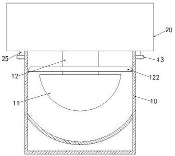
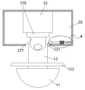
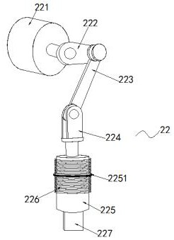
[0021] like Figure 1-4 As shown, the kitchen pounding device according to the embodiment of the present invention includes a pounding tank 10 and a cover plate 20 that is adapted to the pounding tank 10 at the top of the pounding tank 10, and the cover plate 20 and the pounding tank 10 are disassembled and connected, the inside of the cover plate 20 is a hollow structure, the inside of the ramming tank 10 is provided with a ramming hammer 11, and the top of the ramming hammer 11 is fixed with a swing rod 12, and the top of the ramming rod 12 is a The side is provided with an arc-shaped block 121 ...


PUM


Abstract

The invention relates to a smashing device for a kitchen. The smashing device comprises a smashing groove and a cover plate which is located at the top end of the smashing groove and matched with the smashing groove, the cover plate is detachably connected with the smashing groove, the interior of the cover plate is of a hollow structure, a smashing hammer is arranged in the smashing groove, a swing rod is fixed to the top end of the smashing hammer, a first arc-shaped block for increasing the working area of the smashing hammer is arranged on one side of the top of the swing rod, a sliding structure matched with the first arc-shaped block and used for driving the swing rod to swing is arranged on one side of the first arc-shaped block and located in the cover plate, the top end of the swing rod extends into the cover plate, a driving structure used for driving the smashing hammer to move up and down and improving the buffering performance of the smashing hammer is arranged in the cover plate, and a scraping plate matched with the smashing groove is arranged on the outer side of the bottom of the swing rod and located above the smashing hammer in a sleeving mode.

Description

technical field [0001] The invention relates to a pounding device for kitchen, belonging to the technical field of kitchen utensils. Background technique [0002] Many materials in the kitchen need to be smashed to make it more convenient for people to use, such as dried chili, pepper, etc.; but in the daily kitchen, people manually lift the mashing stick and put the dried chili into the material. Manual operation in the tank is extremely inconvenient. At the same time, condiments such as chili and Chinese prickly ash, especially fluffy raw materials like chili, in the mashing production, the material splashes out of the mashing trough, requiring personnel to continuously squeeze out the unmashed material that is extruded to the edge of the mashing chute. The semi-finished products with specified fineness are re-placed under the tamping rod, which increases the labor intensity; at the same time, the working range of the automatic tamping hammer can only move up and down in ...

Claims


Application Information

Patent Timeline
IPC IPC(8): A47J19/04
CPCA47J19/04
Inventor 夏铭
Owner 马鞍山蒹葭电子科技有限公司
Learn More