A road indicator and a mounting method thereof

A technology for signs and roads, applied in the field of signs, can solve the problems of low stability, slow installation speed, and poor fixation of sign boards, and achieve the effects of improving disassembly efficiency, reducing labor intensity, and enhancing strength

Inactive Publication Date: 2018-12-18
ANHUI STARLIGHT LOGO SYST CO LTD
View PDF1 Cites 0 Cited by
  • Summary
  • Abstract
  • Description
  • Claims
  • Application Information

AI Technical Summary

Problems solved by technology

[0003] The purpose of the present invention is to overcome the problems of slow installation speed, poor fixation and low stability of the sign board in the existing road signs, and provide a reasonable structure design, fast installation speed, good fixity, Road signboard with good stability and long service life of signboard and installation method thereof

Method used


Image

  • A road indicator and a mounting method thereof
  • A road indicator and a mounting method thereof
  • A road indicator and a mounting method thereof

Examples


Embodiment 1

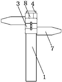
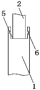
[0025] as attached Figure 1-6 As shown, a road sign, including a column 1, a fixed rod 2, a fixed ring 3 and an end cover 4, is characterized in that: the top of the column 1 is provided with a positioning groove 5, and on the inner wall of the positioning groove 5 A fixed groove 6 is provided, and the fixed rod 2 is vertically arranged in the positioning groove 5. The fixed ring 3 is arranged on the fixed rod 2, and the fixed ring 3 is provided with a sign plate 7, a limit groove 9, a connection The block 10 is provided with a card slot 11 on the inner wall of the limiting groove 9, and a block 12 is provided on the connecting block 10, and a connecting ring 13 and a connecting tooth 14 are provided on the end cover 4, and the connecting ring 13 is connected with the fixed rod 2, and the connecting ring 13 on the end cover 4 is connected with the fixed rod 2. The fixed ring 3 can be suppressed through the end cover 4, so as to avoid the fixed ring 3 between the column 1 and ...

Embodiment 2

[0035] as attached Figure 7 As shown, a road sign, including a column 1, a fixed rod 2, a fixed ring 3 and an end cover 4, is characterized in that: the top of the column 1 is provided with a positioning groove 5, and on the inner wall of the positioning groove 5 A fixed groove 6 is provided, and the fixed rod 2 is vertically arranged in the positioning groove 5. The fixed ring 3 is arranged on the fixed rod 2, and the fixed ring 3 is provided with a sign plate 7, a limit groove 9, a connection The block 10 is provided with a card slot 11 on the inner wall of the limiting groove 9, and a block 12 is provided on the connecting block 10, and a connecting ring 13 and a connecting tooth 14 are provided on the end cover 4, and the connecting ring 13 is connected with the fixed rod 2, and the connecting ring 13 on the end cover 4 is connected with the fixed rod 2. The fixed ring 3 can be suppressed through the end cover 4, so as to avoid the fixed ring 3 between the column 1 and th...


PUM


Abstract

The invention discloses a road indicator plate and a mounting method thereof, Including a column, a fixing rod, a fixingring and an end cap, characterized in that: the top end of the upright post is provided with a positioning groove, The fixing rod is vertically arranged in the positioning groove, the fixing ring is arranged on the fixing rod, a sign plate, a limiting groove and a connecting block are arranged on the fixing ring, a clamping groove is arranged on the inner wall of the limiting groove, a clamping block is arranged on the connecting block, and the end cover is provided with a connecting ring and a connecting tooth, and the connecting ring is connected with the fixing rod. The invention is provided with a buffer groove on the fixing ring, which improves the buffer performanceof the fixing ring and strengthens the strength of the fixing ring through the buffer groove. In addition, the connecting block on the adjacent fixing ring is rotated into the buffer groove to facilitate the separation of the clamping block on the connecting block from the clamping groove, thereby facilitating the separation of the upper and lower adjacent two fixing rings.

Description

technical field [0001] The invention relates to a sign, in particular to a sign for roads and an installation method thereof. Background technique [0002] In daily travel and long-distance travel, you will need to watch the road warning signs on the road and the highway. The road warning signs can give people a clear reminder, which is convenient for people to know where they are and plan their travel routes. However, the road warning signs currently used Sign installation is complicated, assembly is inconvenient, and the stability is not high. For example, the patent application number 201721284730.4 discloses an energy-saving and environmental protection guide sign, which solves the problem that the traditional guide sign has a single function, is not easy to disassemble and assemble, and is difficult to meet the requirements of energy conservation and environmental protection. Requirements, but it has the problems of slow installation speed, poor fixation, and poor stabi...

Claims


Application Information

Patent Timeline
IPC IPC(8): E01F9/623E01F9/65E01F9/677
CPCE01F9/623E01F9/65E01F9/677
Inventor 张建新陈永祥
Owner ANHUI STARLIGHT LOGO SYST CO LTD
Why Eureka
Try Eureka