
Organic biological ventilation fermentation compound fertilizer equipment

A technology of ventilation fermentation and organic biology, which is applied in the directions of organic fertilizer equipment, preparation of organic fertilizer, organic fertilizer, etc., to achieve the effect of improving fermentation effect and preventing adhesion

Inactive Publication Date: 2021-04-30
王栋
View PDF0 Cites 2 Cited by
  • Summary
  • Abstract
  • Description
  • Claims
  • Application Information

AI Technical Summary

Problems solved by technology

[0005] In order to solve the above technical problems, the present invention provides a device for organic biological ventilation and fermentation of compound fertilizers to solve the existing problems

Method used


Image

  • Organic biological ventilation fermentation compound fertilizer equipment
  • Organic biological ventilation fermentation compound fertilizer equipment
  • Organic biological ventilation fermentation compound fertilizer equipment

Examples


Embodiment 1

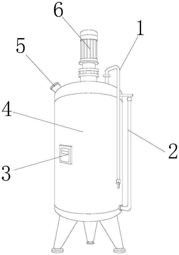
[0029] as attached figure 1 To attach Figure 4 Shown:

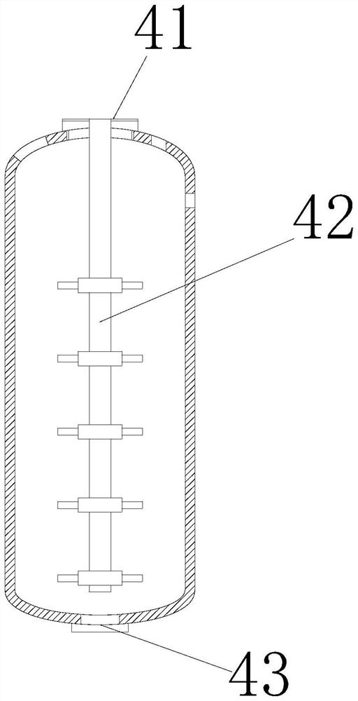
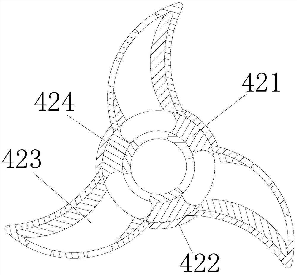
[0030] The invention provides a kind of equipment for organic biological ventilation and fermentation of compound fertilizer. The upper end of the body 4 is flange-connected, the left end of the water inlet pipe 2 is flange-connected to the right end of the body 4, the inner side of the temperature device 3 is installed on the outer side of the body 4, and the lower end of the feed port 5 is embedded and connected to the upper end of the body 4 The lower end of the motor 6 is engaged and connected to the upper end of the fuselage 4. The fuselage 4 includes a fermentation material port 41, a stirring mechanism 42, and a discharge port 43. The inner side of the fermentation material port 41 is embedded with the upper side of the stirring mechanism 42. connection, the upper end of the stirring mechanism 42 is engaged with the lower end of the motor 6 , and the upper end of the discharge port 43 is flange-connected with t...

Embodiment 2

[0036] as attached Figure 5 To attach Figure 8 Shown:

[0037] The present invention provides a device for organic biological ventilation and fermentation of compound fertilizer. The material guide block 232 includes a first chute 321, a moving mechanism 322, and a rebound block 323. The first chute is arranged inside the material guide block 232. 321, the inner side of the moving mechanism 322 is movably engaged with the first chute 321, the outer side of the moving mechanism 322 is engaged and connected to the outer side of the material guide block 232, and the inner side of the material guide block 232 is provided with a rebound block 323, the The first chute 321 is in the shape of a quarter arc, which enables the moving mechanism 322 to be attached to the outer wall of the material guide block. The resilient block 323 is made of silica gel, which increases the resilience of the resilient block 323 .

[0038] Wherein, the moving mechanism 322 includes a cleaning block 2...


PUM


Abstract

The invention provides organic biological ventilation fermentation compound fertilizer equipment, and the equipment structurally comprises an air inlet pipe, a water inlet pipe, a temperature device, a machine body, a feeding port and a motor. The inner side of the air inlet pipe is connected with a flange at the upper end of the machine body, the left end of the water inlet pipe is connected with a flange at the right end of the machine body, and the inner side of the temperature device is installed on the outer side of the machine body. The lower end of the feeding port is fixedly embedded with the upper end of the machine body; the lower end of the motor is connected to the upper end of the machine body in a clamped mode, fermentation raw materials are guided into the fermentation material opening, the conveying pipe is filled with the fermentation raw materials, the fermentation raw materials are input to the stirring tool bit through the limiting block on the outer side of the conveying pipe, and the motor is installed at the upper end of the stirring mechanism and then rotates. Fermentation raw materials are thrown into the compound fertilizer through the baffle under the action of attraction, so that the fermentation raw materials are fully filled with the fertilizer to improve the fermentation effect.

Description

technical field [0001] The invention belongs to the field of biological ventilation and fermentation equipment, and more specifically relates to equipment for organic biological ventilation and fermentation of compound fertilizer. Background technique [0002] Mechanical stirring fermentation equipment is currently the most used type of fermentation tank (accounting for 70%-80% of the total number of fermentation tanks), also known as general-purpose fermentation tank, which uses the function of mechanical stirrer to fill and stir the raw materials , the compound fertilizer needs to pour the fertilizer into the fermenter during the fermentation process, and then add some fermentation raw materials to stir through the stirring mechanism, so that the air and the mash are fully mixed, and the dissolution of oxygen in the mash is promoted to ensure the supply of microorganisms. Oxygen needed for growth, reproduction and fermentation. [0003] Based on the above description, the...

Claims


Application Information

Patent Timeline
IPC IPC(8): C05F17/95C05F17/964C05F17/971C05G1/00
CPCC05G1/00C05F17/95C05F17/964C05F17/971Y02W30/40
Inventor 王栋
Owner 王栋
Learn More