


Quick Research
Generate reliable direction feasibility study reports for your R&D in just a few steps.

Technical Q&A
Discover and master advanced knowledge NOW. Basics, ideas, possibilities, all at once.

Find Solutions
As an expert in R&D theories, this can generate solutions to your technical problems instantly.

Evaluate Feasibility
Analyze your overall solution with one click, know your potential R&D risks in advance.

Monitor Landscape
Get weekly tech updates, stay abreast of the latest tech innovations and key insights.
Automatic paint packaging device
A technology of packaging device and transmission device, which is applied in the field of engineering, can solve the problems of single function and low efficiency, and achieve the effect of synchronous motion speed
- Summary
- Abstract
- Description
- Claims
- Application Information
AI Technical Summary
Problems solved by technology
Method used
Image

Examples
specific Embodiment approach 1
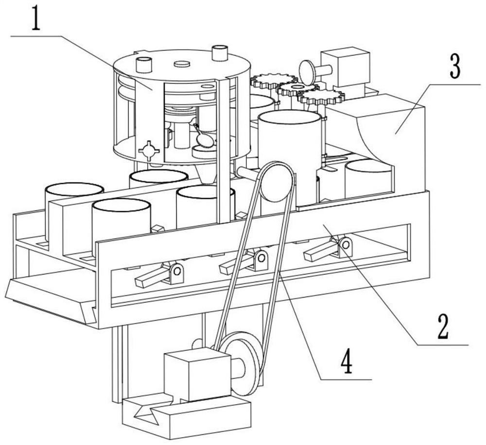
[0026] Combine below Figure 1-10 Describe this embodiment, an automatic paint packaging device, including a liquid outlet device 1, a transmission device 2, a capping device 3, and a belt 4, the liquid outlet device 1 is connected to the transmission device 2, and the transmission device 2 is connected to the capping device 3 phases are connected, the liquid outlet device 1 is connected with the belt 4, and the transmission device 2 is connected with the phase.
specific Embodiment approach 2
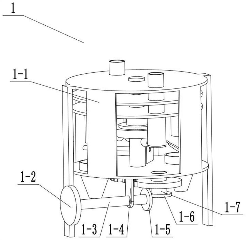
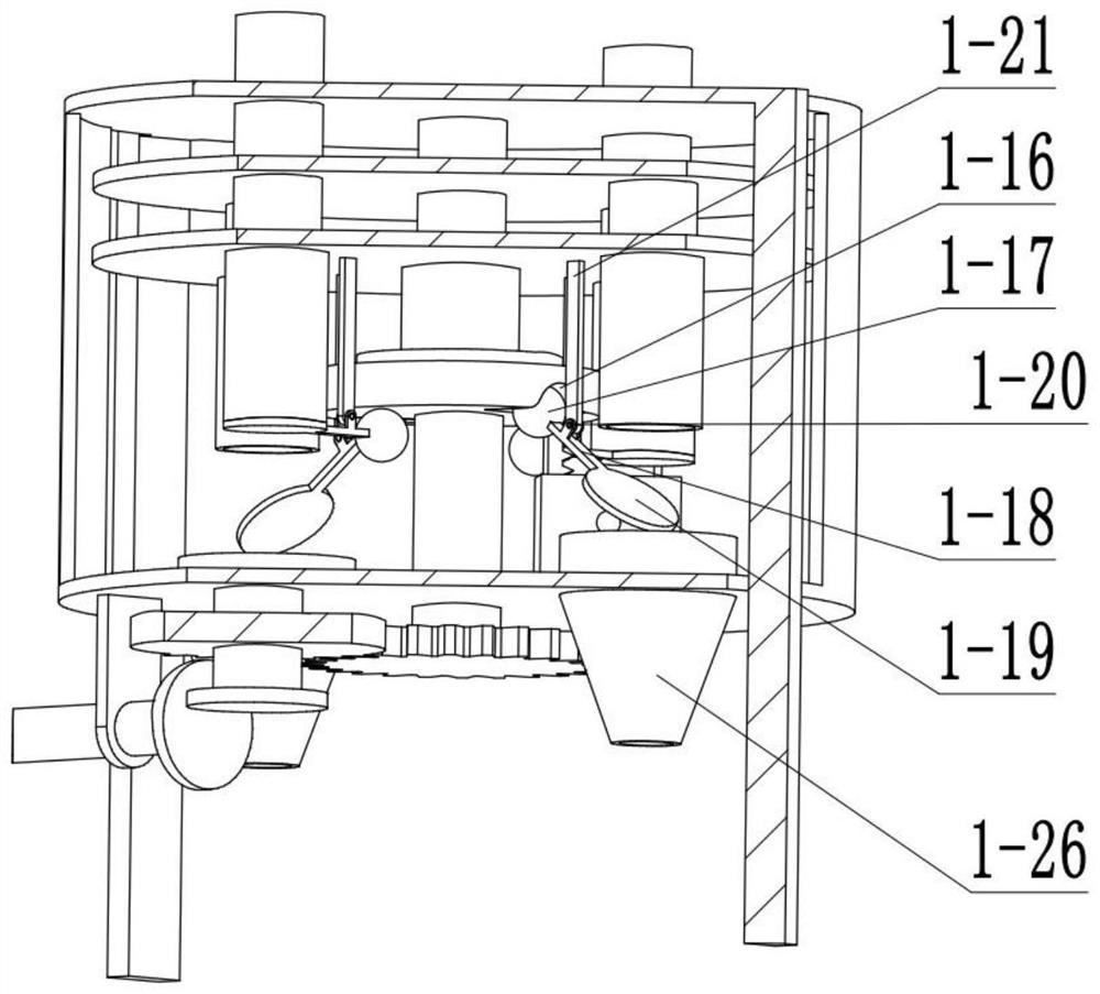
[0028] Combine below Figure 1-10Describe this embodiment, this embodiment will further explain Embodiment 1, the liquid outlet device 1 includes a housing bracket 1-1, a runner 1-2, a linkage column 1-3, a bracket 1-4, a rotary Wheel two 1-5, runner three 1-6, linkage column two 1-7, half gear one 1-8, gear one 1-9, linkage column three 1-10, disc one 1-11, container one 1 -12, disc two 1-13, container two 1-14, functional disc 1-15, round groove 1-16, small ball 1-17, connecting rod one 1-18, round cover 1-19, hinge Column one 1-20, connecting rod two 1-21, tooth column 1-22, gear two 1-23, connecting column one 1-24, turn knob 1-25, outlet pipe 1-26, inlet pipe 1- 27. The runner one 1-2 is fixedly connected with the linkage column one 1-3, the linkage column one 1-3 is rotationally connected with the bracket one 1-4, the shell bracket 1-1 is fixedly connected with the bracket one 1-4, and the linkage column one 1-3 is fixedly connected with runner 2 1-5, runner 2 1-5 is e...
specific Embodiment approach 3
[0031] Combine below Figure 1-10 Describe this embodiment, this embodiment will further explain Embodiment 1, the transmission device 2 includes a transmission bracket 2-1, a packaging box 2-2, a motor 2-3, a base boss 2-4, and a runner 4 2-5, runner five 2-6, connecting rod three 2-7, bracket two 2-8, fixed block 2-9, gear block 2-10, half gear two 2-11, function bump 2-12, Function bar 2-13, hinge column 2 1-14, slide block 1-15, transmission bracket 2-1 is slidably connected with packing box 2-2, motor 1 2-3 is slidably connected with base boss 2-4, motor 1 2-3 is fixedly connected with runner four 2-5, runner four 2-5 is connected with runner five 2-6, runner five 2-6 is fixedly connected with connecting rod three 2-7, connecting rod three 2- 7 is rotationally connected with bracket two 2-8, bracket two 2-8 is fixedly connected with transmission bracket 2-1, fixed block 2-9 is fixedly connected with transmission bracket 2-1, gear block 2-10 is connected with half gear tw...
PUM
 Abstract
Description
Claims
Application Information
 - R&D Engineer
- R&D Manager
- IP Professional
- Industry Leading Data Capabilities
- Powerful AI technology
- Patent DNA Extraction
Browse by: Latest US Patents, China's latest patents, Technical Efficacy Thesaurus, Application Domain, Technology Topic, Popular Technical Reports.
© 2024 PatSnap. All rights reserved.Legal|Privacy policy|Modern Slavery Act Transparency Statement|Sitemap|About US| Contact US: help@patsnap.com