Novel drop-out quick breaker

A drop-type, quick-breaker technology, applied in electrical components, circuits, emergency protection devices, etc., can solve problems such as line reclosing failure, blockage, and diversion discharge heating, etc., to achieve reliable fault current cutoff, reduce use costs, and conduct electricity. Ability-enhancing effect

Pending Publication Date: 2021-04-27
中船安智(湖北)科技有限公司
View PDF1 Cites 0 Cited by
  • Summary
  • Abstract
  • Description
  • Claims
  • Application Information

AI Technical Summary

Problems solved by technology

[0005] (1) When a short-circuit fault occurs in the equipment at the back stage, the time before the arc of the melt is broken is long, and there is a great possibility that the melt cannot be fused before the outlet switch of the substation cuts off the fault current, resulting in the failure of the drop-out fuse to be correct. Isolate the fault point, when the line recloses, the faulty device is short-circuited again, resulting in the failure of line reclosing and a power outage on the whole line
[0006] (2) Affected by the arc extinguishing medium and the gas-producing material on the inner wall of the melting tube, the gas production is small and the rate is low. When the arc is generated, the arc cannot be blown and cooled effectively, resulting in poor arc extinguishing ability
[0007] (3) Drop-out fuses are generally installed outdoors. Affected by the wind and rain in the natural environment, the arc suppression tube in the melting tube is prone to moisture expansion, and the inner diameter is reduced or blocked.
When a fault occurs, the fuse is blown, but due to the reduction in the inner diameter of the arc suppression tube or blockage, the blockage will clamp the fused fuse connection wire, resulting in the fuse tube still maintaining its original state for a long time when the fuse is blown. State, can not fall quickly, and the arc is not cut off in the fusion tube, and finally a continuous arc occurs, causing the fuse to burn out, resulting in the failure of line reclosing and a power outage across the line
[0008] (4) There is no communication function. When a line fault occurs, the grid maintenance personnel cannot quickly know the fault location, and a certain amount of troubleshooting time is required, thereby prolonging the power outage time caused by the line fault
The above-mentioned device uses the power of gunpowder explosion to blow the fuse directly. Although this method is direct and fast, but the gunpowder is installed on the guide bar, under the influence of the electromagnetic field generated by the changing large current, the gunpowder may explode and cause malfunction. The guide bar will generate heat under the action of changing high current, and it may also cause the explosion of gunpowder, resulting in malfunction; the failure of the entire device, resulting in serious losses
The above-mentioned patent adopts the method of blasting and turning the guide row to form a fracture, which requires a large space, so the product is too large
In addition, after the switch is exploded, the entire switch needs to be replaced, and the cost of use is too high
[0012] In the prior art, a drop-type instant breaker based on a vacuum interrupter is also disclosed, which can quickly (within 25ms), accurately and reliably cut off the fault line, but the power detection module and vacuum interrupter in this product They are all installed on the fusion tube, which makes the fuse-carrying parts very heavy (about 6Kg). After a fault occurs, the insulating rod cannot be used to operate on the ground when replacing the fuse-carrying parts. Low efficiency and high labor costs
At the same time, the carrier melt is disposable. After the action, it needs to be replaced with a new carrier melt. Together with the detection module and the arc extinguishing device, the cost of consumables is very high.

Method used


Image

  • Novel drop-out quick breaker
  • Novel drop-out quick breaker
  • Novel drop-out quick breaker

Examples


Embodiment Construction

[0052] The present invention will be further described in detail below in conjunction with specific examples to facilitate a clear understanding of the present invention, but they do not limit the present invention.

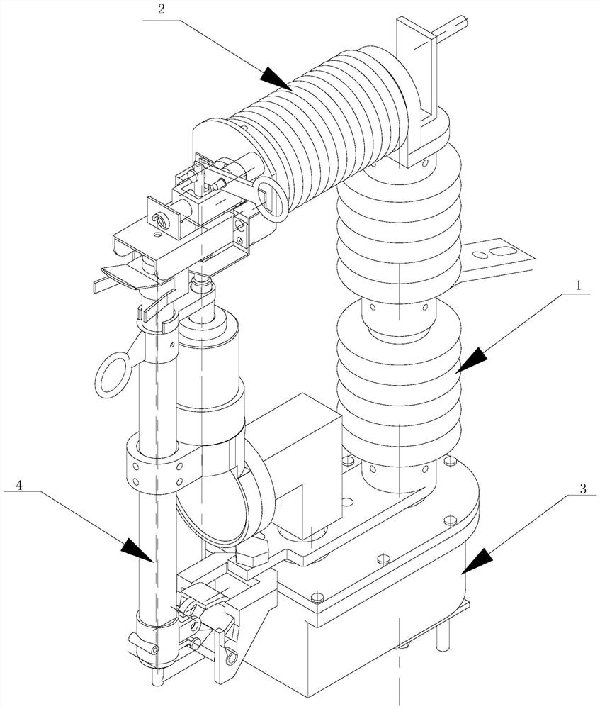
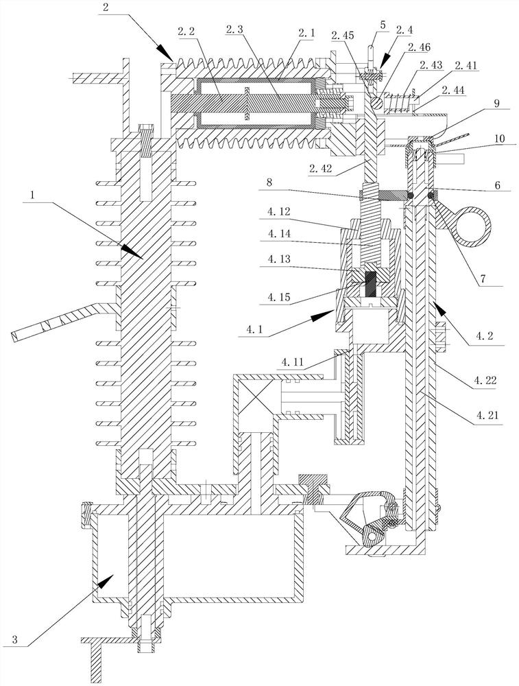
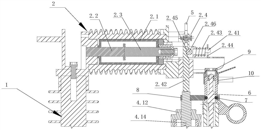
[0053] Such as figure 1 and figure 2 As shown, a new drop-type instant breaker of the present invention includes a mounting base 1, a vacuum arc extinguishing device 2, a detection control device 3, and a conductive device 4; the vacuum arc extinguishing device 2 is horizontally installed on the mounting base 1 , the conductive member device 4 is installed vertically on the mounting base 1, the vacuum arc extinguishing device 2 includes a vacuum tube 2.1, a static contact 2.2 and a moving contact 2.3 arranged in the vacuum tube 2.1, and a control moving contact 2.3 Disconnected and reset traction mechanism 2.4;

[0054] The conductor device 4 includes a conductor mechanism 4.2 and a push mechanism 4.1 installed on the conductor mechanism 4.2. The lower end of ...


PUM


Abstract

The invention relates to a drop-out quick breaker. The quick breaker comprises a mounting base, a vacuum arc extinguishing device, a detection control device and a conductive piece device, wherein the vacuum arc extinguishing device comprises a vacuum tube, a static contact and a moving contact which are arranged in the vacuum tube, and a traction mechanism which controls the moving contact to be disconnected and reset; the conductive piece device comprises a conductive body mechanism and a pushing mechanism fixed on the conductive body mechanism, the lower end of the conductive body mechanism is rotatably hung at the bottom of the mounting seat, the upper end of the conductive body mechanism is clamped on a conductive static contact on the mounting seat, and the conductive body mechanism comprises a conductive wire unit and a drop control unit; the pushing mechanism can drive the traction mechanism to drive the moving contact to be separated from the static contact; the pushing mechanism drives the traction mechanism and drives the falling control unit at the same time to realize falling of the conductor mechanism. The drop-out quick breaker can quickly, accurately and reliably cut off a fault line, prevents switching-on and reclosing failures of an outgoing line switch of a transformer substation, and enables a fault-free line to supply power normally.

Description

technical field [0001] The invention belongs to the technical field of circuit breakers, and in particular relates to a novel drop-type quick breaker. Background technique [0002] At present, drop-out fuses are installed in medium and low-voltage distribution lines and distribution transformers as short-circuit protection switches, which can reduce the scope of power outages, because there is an obvious disconnection point, which has the function of isolating switches, and provides protection for maintenance section lines and The equipment creates a safe working environment and improves the safety of maintenance personnel. It is installed on the distribution transformer and can be used as the main protection of the distribution transformer. It is widely used in medium and low voltage distribution lines and distribution transformers. [0003] The working principle of the drop-out fuse is that the moving contacts at both ends of the fuse tube are fastened by the fuse (melt),...

Claims


Application Information

Patent Timeline
IPC IPC(8): H01H85/02H01H85/22H01H85/38
CPCH01H85/02H01H85/22H01H85/38
Inventor 黄生华王国博贾云东丁建龙蔡昊许三详
Owner 中船安智(湖北)科技有限公司
Why Eureka
Try Eureka