Pin shaft transferring and transporting device

A transportation device and pin shaft technology, which is applied in transportation and packaging, multi-axle trolleys, trolleys, etc., can solve the problems of unfavorable economy and flexibility of forklifts, unfavorable selection and use of users, scratches and scratches on the paint surface, etc. Storage, easy storage and removal, strong practical effect

Active Publication Date: 2021-04-27
山东华伟重特机械有限公司
View PDF4 Cites 1 Cited by
  • Summary
  • Abstract
  • Description
  • Claims
  • Application Information

AI Technical Summary

Problems solved by technology

[0003] Traditional pins are often placed in a box during transfer and transportation, which is likely to cause bumps and scratches on the paint surface. It is also not conducive to the selection and use of users when they are delivered to users. At the same time, it is not conducive to the economy to use forklifts when there are too many deliveries. and flexibility, so we propose a pin transfer transport device to solve the above-mentioned problems

Method used


Image

  • Pin shaft transferring and transporting device
  • Pin shaft transferring and transporting device
  • Pin shaft transferring and transporting device

Examples


Embodiment 1

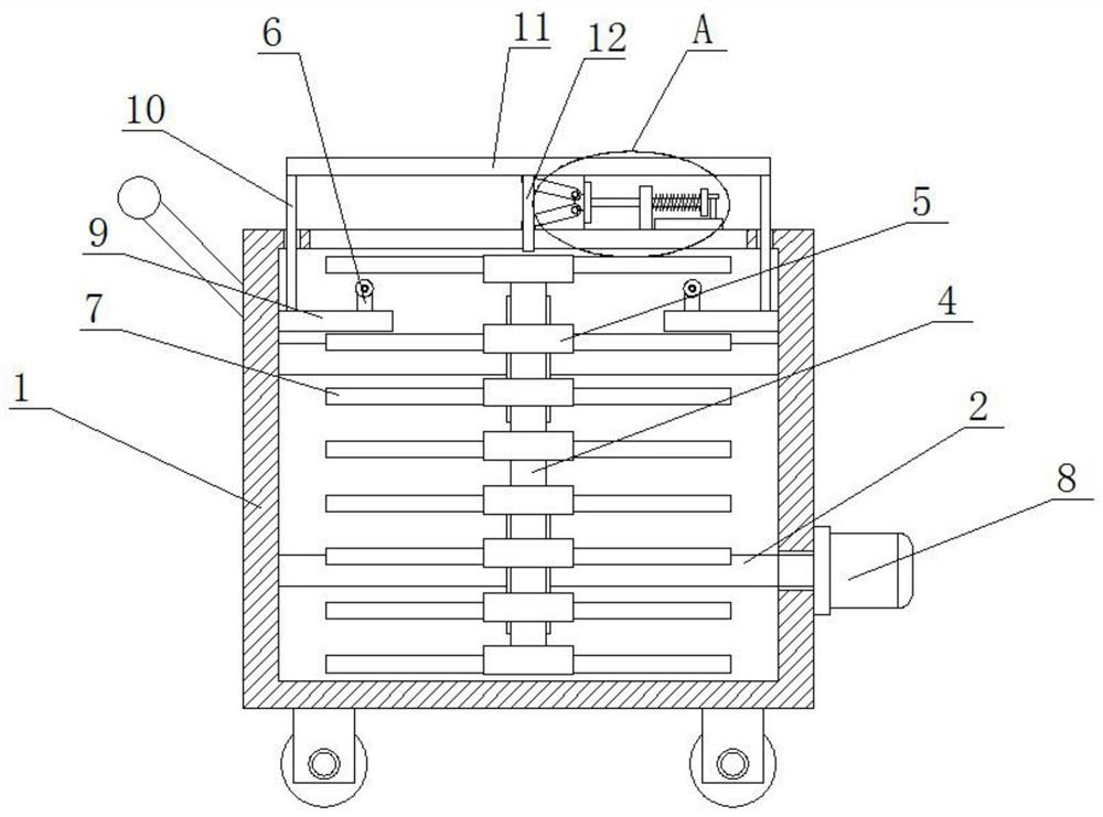
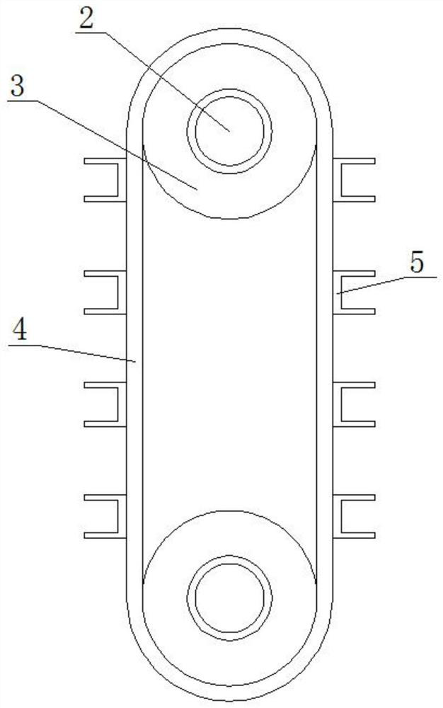
[0025] refer to Figure 1-5 In this embodiment, a pin shaft transfer transport device is proposed, including a transport box 1, wheels are rotatably connected to the four corners of the bottom of the transport box 1, and a handle is fixedly installed on the top of one side of the transport box 1. The transport box 1 Two rotating shafts 2 are symmetrically rotated on the inner wall of the transport box 2, and a turntable 3 is fixedly installed on the two rotating shafts 2, and the same transmission belt 4 is connected to the two turntables 3, and a driving belt 4 is fixedly installed on the bottom of the other side of the transport box 1. Motor 8, and the drive motor 8 is fixedly connected to one end of the rotating shaft 2 located below, and a plurality of U-shaped plates 5 are fixedly installed at equal intervals on the transmission belt 4, and a clamping assembly is arranged on the U-shaped plate 5, and the clamping assembly is clamped The pin shaft 7 is installed, and the t...

Embodiment 2

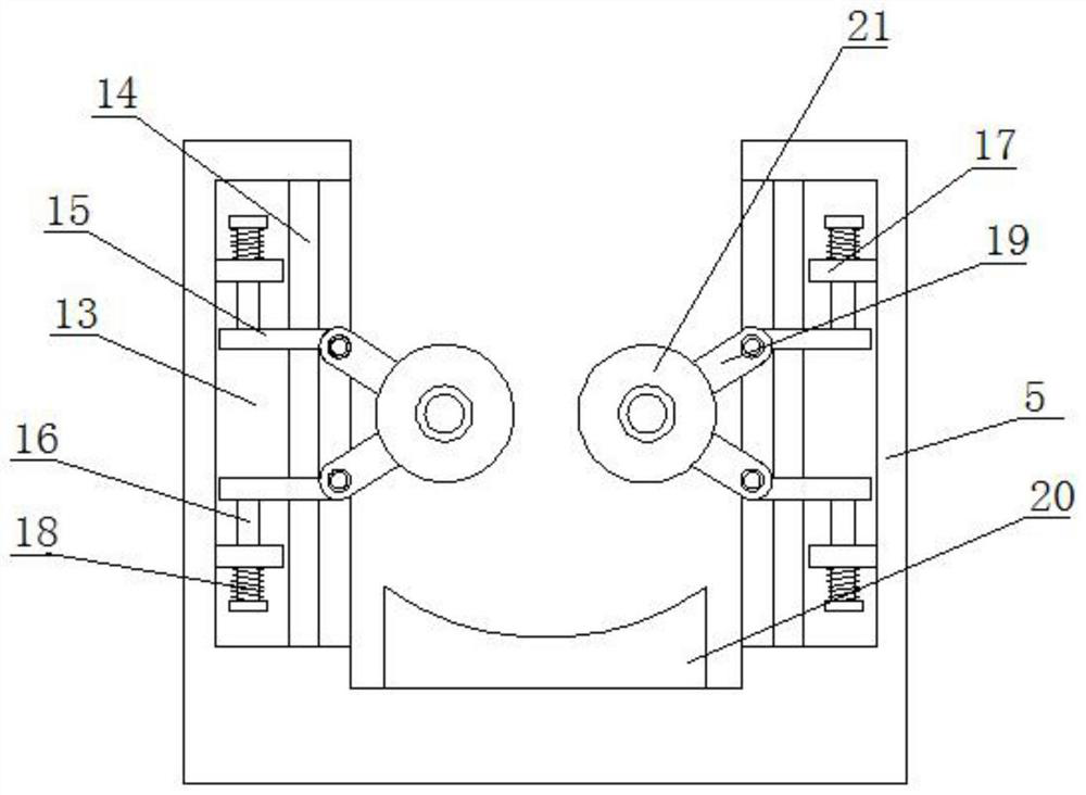
[0028] In this embodiment, the clamping assembly includes connecting grooves 13 provided on the inner walls of both sides of the U-shaped plate 5, and two sliding plates 15 are symmetrically slidably connected in the connecting groove 13, and one side of the two sliding plates 15 is rotationally connected. Connecting rod 19 is arranged, and one end of two connecting rods 19 all extends to the outside of connecting groove 13 and is connected with same limit wheel 21 in rotation, and limit plate 20 is fixedly installed on the inner wall of U-shaped plate 5, and two limit Position wheel 21 and limit plate 20 are all clamped with bearing pin 7, utilize two limit wheels 21 and limit plate 21 to clamp pin shaft 7 conveniently.

[0029] In this embodiment, a sliding bar 14 is fixedly installed on the inner wall of the connecting groove 13, and two sliding plates 15 are both slidably sleeved on the sliding bar 14, and two fixing plates are symmetrically fixedly installed on one side of...


PUM


Abstract

The invention belongs to the field of transporting devices, particularly relates to a pin shaft transferring and transporting device, and aims to solve the problems that existing pin shafts of various models are collided and scratched in the transferring and transporting process and in the using process, set-by-set distribution has no tool distribution disorder and is not beneficial to selection. A following scheme is disclosed: the pin shaft transferring and transporting device comprises a transporting box; wheels are rotatably connected to the four corners of the bottom of the transportation box correspondingly, a handle is fixedly mounted at the top of one side of the transportation box, two rotating shafts are symmetrically and rotatably connected to the inner wall of the transportation box, and rotating discs are fixedly mounted on the two rotating shafts correspondingly. According to the pin shaft transferring and transporting device, a plurality of U-shaped plates are arranged, it is convenient for storing and limiting of a plurality of pin shafts, the plurality of pin shafts cannot make contact with one another, friction cannot happen, the pin shafts can be conveniently taken out of the transportation box, the pin shafts can be conveniently taken out, and therefore the pin shafts can be conveniently stored and taken out when the pin shaft transportation box is used, and the pin shaft transferring and transporting device has very high practicability in use.

Description

technical field [0001] The invention relates to the technical field of transportation devices, in particular to a pin shaft transfer transportation device. Background technique [0002] The pin shaft is a kind of standardized fastener, which can be statically fixed and connected, and can also move relative to the connected parts. It is mainly used at the hinge of two parts to form a hinge connection. The pin shaft is usually locked with a cotter pin, which is reliable in operation and easy to disassemble. [0003] Traditional pins are often placed in a box during transfer and transportation, which is likely to cause bumps and scratches on the paint surface. It is also not conducive to the selection and use of users when they are delivered to users. At the same time, it is not conducive to the economy to use forklifts when there are too many deliveries. and flexibility, so we propose a pin shaft transfer transport device for solving the above-mentioned problems. Contents o...

Claims


Application Information

Patent Timeline
Patent Type & Authority Applications(China)
IPC IPC(8): B62B3/04B62B3/02
CPCB62B3/04B62B3/02B62B2205/006
Inventor 张霞高祥蒙
Owner 山东华伟重特机械有限公司
Why Eureka
Try Eureka