Equidistant cutting device for plastic pipe
A technology of equidistant cutting and plastic pipes, applied in metal processing, etc., can solve problems such as low degree of automation, low equipment integrity, and complicated operation steps, and achieve the effects of improving transportation speed, avoiding accidents, and facilitating storage
- Summary
- Abstract
- Description
- Claims
- Application Information
AI Technical Summary
Problems solved by technology
Method used
Image

Examples
Embodiment 1
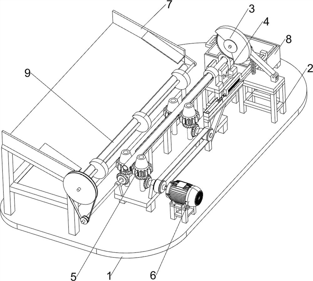
[0061] A device for isometric cutting of plastic pipes such as figure 1 As shown, it includes a base plate 1, a support frame 2, a material cutting mechanism 3 and a clamping mechanism 4. The left and right sides of the rear portion of the base plate 1 are provided with a support frame 2, and the support frame 2 is provided with a material cutting mechanism 3. The support frame 3 and the A clamping mechanism 4 is arranged between the material cutting mechanisms 4 .
[0062] People place the material on the clamping mechanism 4, and manually operate the material cutting mechanism 3 to cut the material. After the material cutting is completed, the manual operation of the material cutting mechanism 3 is stopped.
Embodiment 2
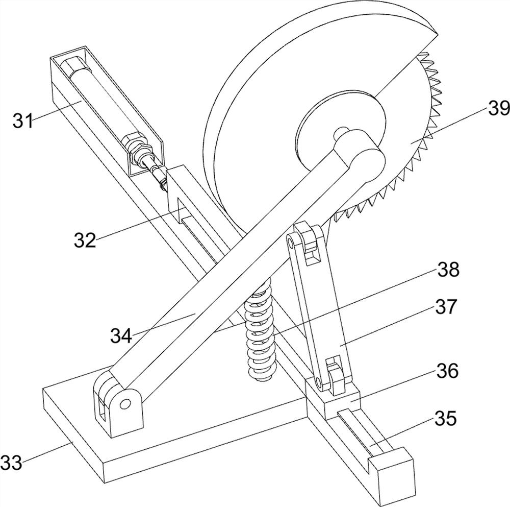
[0064] On the basis of Example 1, such as figure 2 As shown, the material cutting mechanism 3 includes a cylinder 31, a sliding push rod 32, a base 33, a support rod 34, a slide rail 35, a slider 36, a connecting rod 37, a return spring 38 and a cutting machine 39, and the support frame 2 is provided with Base 33, base 33 right part rotation type is connected with support rod 34, is connected with cutting machine 39 on the support rod 34, base 33 left rear part is provided with slide rail 35, base 33 left front part is provided with cylinder 31, cylinder 31 The rear side is connected with a slide push rod 32, and the rear portion of the slide push rod 32 is provided with a slide block 36, and the slide push rod 32 and the slide block 36 are slidably connected with the slide rail 35. A connecting rod 37 is rotatably connected, and a return spring 38 is arranged between the middle part on the left side of the base 33 and the support rod 34 .
[0065] When the material is trans...
Embodiment 3
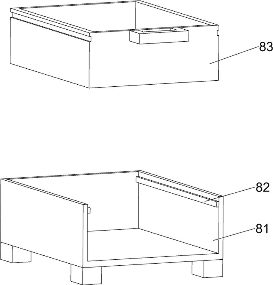
[0067] On the basis of Example 2, such as Figure 3 to Figure 6 As shown, the clamping mechanism 4 includes a fixed guide block 41, a vise seat 42, a screw positioning rod 43, a double-ended screw 44, a grooved rack 45, a transmission gear 46 and a jaw plate 47. The front and rear sides are all provided with fixed guide blocks 41, the middle part of the left support frame 2 is provided with a vise seat 42, the left and right sides of the vise seat 42 are slidingly provided with a jaw plate 47, and the middle part of the vise seat 42 is provided with a screw for positioning. Rod 43, the double-ended screw rod 44 is connected with the double-ended screw rod 44 in rotation on the screw rod positioning rod 43, and the double-ended screw rod 44 is threadedly connected with the jaw plate 47. The right side of the double-ended screw rod 44 is provided with transmission gear 46, and the sliding push rod 32 is provided with a belt The grooved rack 45, the grooved rack 45 is meshed with t...
PUM
 Abstract
Description
Claims
Application Information
 - R&D
- Intellectual Property
- Life Sciences
- Materials
- Tech Scout
- Unparalleled Data Quality
- Higher Quality Content
- 60% Fewer Hallucinations
Browse by: Latest US Patents, China's latest patents, Technical Efficacy Thesaurus, Application Domain, Technology Topic, Popular Technical Reports.
© 2025 PatSnap. All rights reserved.Legal|Privacy policy|Modern Slavery Act Transparency Statement|Sitemap|About US| Contact US: help@patsnap.com