Hot air baffle structure for cooking device and oven

A technology of baffle structure and cooking device, which is applied in applications, cooking utensils, kitchen utensils, etc. It can solve the problems of decreased uniformity of gas field, increased wind resistance of fan blades of hot air blower, air flow loss, etc., so as to ensure the uniformity of air intake Sexuality, avoiding loss of air volume, avoiding the effect of airflow escape

Active Publication Date: 2021-04-27
NINGBO FOTILE KITCHEN WARE CO LTD
View PDF8 Cites 0 Cited by
  • Summary
  • Abstract
  • Description
  • Claims
  • Application Information

AI Technical Summary

Problems solved by technology

In this patent, the air inlet is formed by circular small holes, and the actual air inlet area of ​​the air inlet can be changed by moving the air inlet shutter, although the circular small holes on the air inlet can be partially covered by the air inlet shutter. The purpose of adjusting the size of the air intake area is to realize the adjustment of the air intake volume, and the air inlet of the hot air baffle uses the central negative pressure generated by the rotation of the hot air blower as the power to inhale the air in the inner tank, so through the left and right sides of the air inlet baffle The method of moving to change the air inlet area reduces the uniformity of the air field at the air inlet of the hot air baffle, which in turn affects the uniformity of the air outlet of the hot air blower and the uniformity of the air outlet of the hot air baffle
In addition, in the prior art, the airflow in the liner directly enters the air inlet along the front and rear directions, so that the airflow entering from the air inlet hits the fan blades of the hot air blower vertically, which causes the airflow loss at the air inlet on the one hand, On the other hand, the air resistance of the fan blades of the hot air blower is increased, which affects the circulating air volume of the hot air blower per unit time.

Method used


Image

  • Hot air baffle structure for cooking device and oven
  • Hot air baffle structure for cooking device and oven
  • Hot air baffle structure for cooking device and oven

Examples


Embodiment Construction

[0028] The present invention will be further described in detail below in conjunction with the accompanying drawings and embodiments.

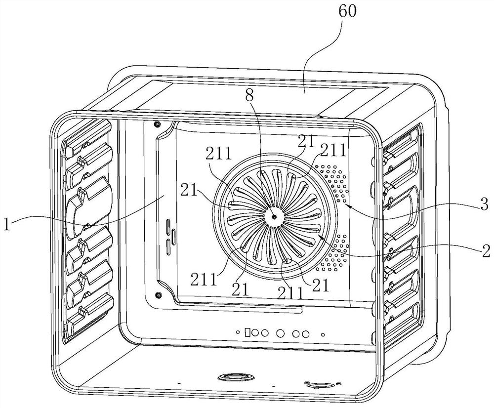
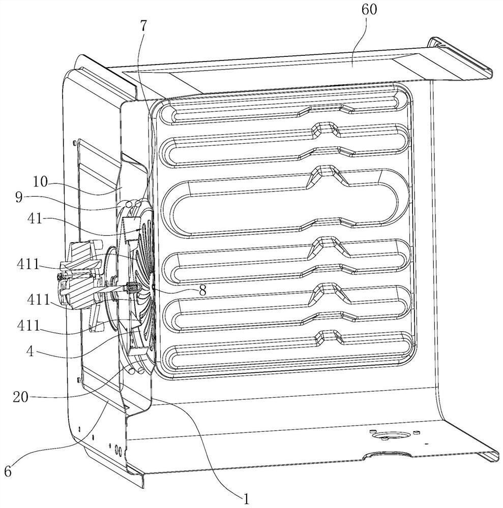
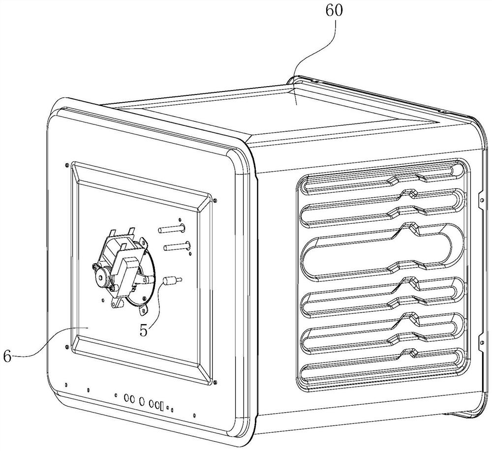
[0029] Such as Figure 1-7 As shown, an oven includes a hot air baffle structure, the hot air baffle structure includes a hot air baffle 1, and the hot air baffle 1 is covered on the back plate 6 of the inner container 60 to form a hot air chamber 10, the hot air chamber Heat fan blade 7 is installed in 10, and the outer periphery of this heat fan blade 7 is provided with heating pipe 9, and the center of above-mentioned hot air baffle plate 1 is provided with and is opposite with above-mentioned heat fan blade 7 front and back and concentric axis (being both The circular air inlet 2 is provided with the center of circle on the same straight line), and the peripheral side of the air inlet 2 is provided with an air outlet 3 . There are two kinds of present embodiment, the shape of the above-mentioned heating tube 9 is circular.

[0030] Furth...


PUM


Abstract

The invention relates to a hot air baffle structure for a cooking device and an oven. An air inlet of a hot air baffle is composed of air inlet holes, each air inlet hole is in a long strip shape and extends from inside to outside along the plate face, where the air inlet is located, of the hot air baffle, and the width of each air inlet hole is gradually increased from inside to outside; the air inlet holes rotate in the same direction in the circumferential direction from inside to outside, so that when the hot air fan blades rotate, airflow entering the air inlet holes can be prevented from escaping to the maximum extent, and the air inlet amount of the air inlet is increased; and when the adjusting grid plate rotates, the air inlet holes can be completely opened by being opposite to the adjusting grid holes in the adjusting grid plate in the front-back direction; or the air inlet holes are shielded through an adjusting shielding surface of the adjusting grid plate, that is, the air inlet areas of the air inlet holes can be changed in the circumferential direction along with the rotation of the adjusting grid plate; and compared with an existing translation mode, the air inlet uniformity can be effectively guaranteed on the basis that the air inlet area of the air inlet is adjusted.

Description

technical field [0001] The invention relates to the field of cooking devices, in particular to a hot air baffle structure and an oven for the cooking device. Background technique [0002] A hot air baffle is generally installed in the inner container of cooking devices with baking functions such as an oven and a steam oven. The hot air baffle has an air inlet and an air outlet, and the back plate of the inner container and the hot air baffle form a hot air chamber , the hot air chamber is respectively provided with a hot air blower and a heating pipe, and the shape of the heating pipe is annular and is arranged around the outer periphery of the fan blade of the hot air blower. In this way, the hot air blower rotates in the hot air chamber to generate negative pressure, and the airflow in the inner tank enters the hot air chamber under the effect of negative pressure to be heated, and the heated hot air flows from the hot air baffle under the action of the centrifugal force o...

Claims


Application Information

Patent Timeline
IPC IPC(8): A47J37/06A47J36/00
CPCA47J37/06A47J36/00
Inventor 谭万福王丁姚青卜玲娟
Owner NINGBO FOTILE KITCHEN WARE CO LTD
Why Eureka
Try Eureka