
Method for disassembling and assembling blade type high-pressure fan of turbine generator

A turbo-generator and vane-type technology, which is applied in the manufacture of stator/rotor bodies, etc., can solve the problems of mechanical injury risk of overhaul personnel, low maintenance efficiency of turbo-generator sets, and low efficiency of turbo-generator maintenance, achieving The effect of shortening the overhaul period, shortening the driving time, and increasing the space for disassembly and assembly operations

Active Publication Date: 2021-04-23
JIANGSU NUCLEAR POWER CORP
View PDF7 Cites 0 Cited by
  • Summary
  • Abstract
  • Description
  • Claims
  • Application Information

AI Technical Summary

Problems solved by technology

[0004] (1) Due to the small gap between the fan cover and the fan seat ring of the high-pressure fan, when the special tool for turning the fan cover is put in, it needs to be adjusted several times with other auxiliary tools before it can be put in, and two pieces of fan cover disassembly rings need to be installed. It takes a long time to install, resulting in low efficiency of turbogenerator maintenance;
[0005] (2) During the disassembly and assembly of the high-pressure fan, the generator rotor needs to be rotated several times, and there is a greater risk of mechanical injury to maintenance personnel and damage risks to important components, such as moving fan blades and static fan blades;
[0006] (3) The rotor of the generator needs to be operated by the crane of the steam turbine workshop. During the overhaul period, it belongs to the main maintenance line of the steam turbine workshop. The maintenance efficiency of the steam turbine generator set is low, which seriously delays the overhaul period;
[0007] (4) The generator rotor has a large number of moving fan blades. Currently, 1 / 4 partitions are used as the basic unit for disassembly and assembly, and there is a high risk of foreign objects falling into the high-pressure fan during disassembly.

Method used


Image

  • Method for disassembling and assembling blade type high-pressure fan of turbine generator
  • Method for disassembling and assembling blade type high-pressure fan of turbine generator
  • Method for disassembling and assembling blade type high-pressure fan of turbine generator

Examples


Embodiment 1

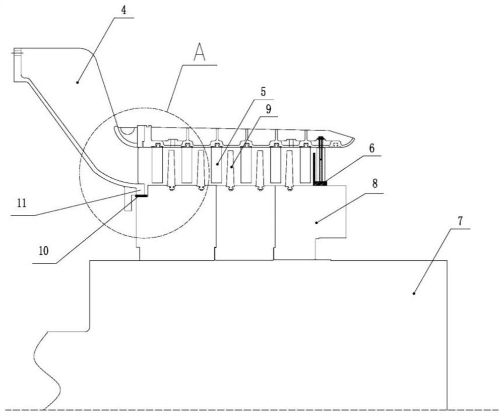
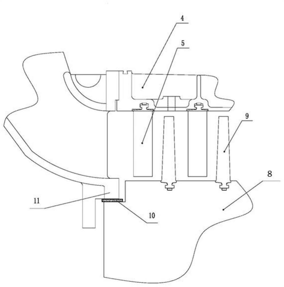
[0047] Such as Figure 1-3 As shown, a method for disassembling a turbogenerator blade-type high-pressure fan provided by the present invention, the method includes the following steps:

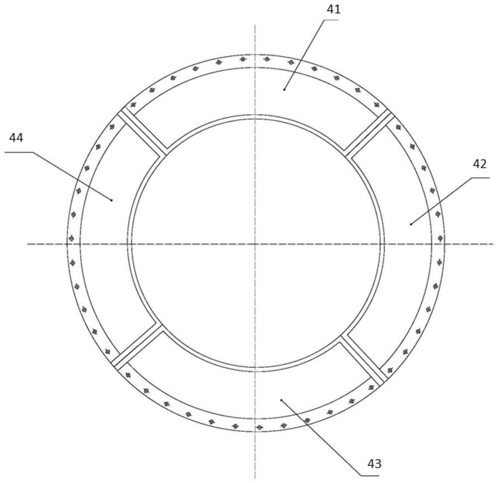
[0048] Step (A1), removing the upper fan cover 41;

[0049] Step (A2), install a fan cover dismounting ring 6 at the tail of the high-pressure fan cover 4, and install a sliding gasket 10 in the gap between the high-pressure fan cover radial limit block 11 and the fan seat ring 8, for reducing Small sliding part friction;

[0050] Step (A3), rotate the remaining fan cover clockwise, place the left fan cover 44, the lower fan cover 43 and the right fan cover 42 directly above and remove them;

[0051] Step (A3.1), rotate the remaining 3 fan covers clockwise so that the left fan cover 44 is placed directly above and removed;

[0052] Step (A3.2), rotate the remaining 2 fan covers clockwise so that the lower fan cover 43 is placed directly above and removed;

[0053] Step (A3.3), rotate the ...

Embodiment 2

[0058] Such as Figure 1-3 As shown, the present invention provides a method for installing a turbogenerator blade-type high-pressure fan, the method comprising the following steps:

[0059] Step (B1), installing all moving fan blades 9;

[0060] Step (B2), install a fan cover dismounting ring 6 at the tail of the high-pressure fan cover 4, install a sliding gasket 10 in the gap between the high-pressure fan cover radial limit block 11 and the fan seat ring 8, for reducing Small sliding part friction;

[0061] Step (B3), install the left fan cover 44, the lower fan cover 43 and the right fan cover 42 sequentially directly above, and rotate each fan cover clockwise by 90°;

[0062] Step (B3.1), install the left flap fan cover 44 directly above and rotate it 90° clockwise;

[0063] Step (B3.2), install the lower flap fan cover 43 directly above and rotate it 90° clockwise;

[0064] Step (B3.3), install the right flap fan cover 42 directly above and rotate it 90° clockwise;

...


PUM


Abstract

The invention belongs to the technical field of steam turbine generator maintenance, and relates to methods for disassembling and assembling a blade type high-pressure fan of a steam turbine generator. The dismounting method of the blade type high-pressure fan of the turbine generator comprises the steps that: an upper fan cover is dismounted; a fan cover dismounting ring and a sliding gasket are mounted; the remaining fan covers are clockwise rotated, so that the left fan cover, the lower fan cover and the right fan cover can be arranged over the blade type high-pressure fan in sequence and are detached; a special tool is removed; and all movable fan blades are dismantled. The assembling method of the blade type high-pressure fan of the turbine generator comprises the steps that: all movable fan blades are installed; a fan cover dismounting ring and a sliding gasket are mounted; a left fan cover, a lower fan cover and a right fan cover are sequentially mounted right above the blade type high-pressure fan, and the blade type high-pressure fan is rotated clockwise by 90 degrees when each fan cover is mounted; a special tool is removed; and an upper fan cover is arranged right above the high-pressure fan. According to the methods, the disassembling and assembling operation process of the blade type high-pressure fan can be simplified, and the disassembling and assembling efficiency of the high-pressure fan is effectively improved.

Description

technical field [0001] The invention belongs to the technical field of turbogenerator maintenance, and in particular relates to a method for disassembling and assembling a vane-type high-pressure fan of a turbogenerator. Background technique [0002] At present, in the internal cooling system of the turbogenerator at home and abroad, the high-pressure fan is used as the power source for the internal cooling of the generator, so that the internal cooling medium of the generator generates a higher pressure, thereby realizing the internal circulation cooling function of the internal cooling system of the generator, driving The cooling medium cools the stator winding, stator core, rotor winding, rotor core and other parts of the generator to ensure the normal operation of the turbo generator. The high-pressure fan is composed of a certain number of moving blades on the fan seat ring and four-petal high-pressure fan cover, including the upper fan cover, the right fan cover, the l...

Claims


Application Information

Patent Timeline
Patent Type & Authority Applications(China)
IPC IPC(8): H02K15/02
Inventor 章勇佟小明薛杰吕泓瑄严皓翔孙凯于霄吴兴文李冬玉高玉好刘本生蒋晓鹏雷成何威俞学成张亚峰黄怡涵
Owner JIANGSU NUCLEAR POWER CORP
Learn More