Solar cell module assembling device and assembling method thereof

A technology for solar cells and assembling devices, applied in the field of solar cells, can solve the problems of cumbersomeness, easy deformation of the frame, overflow of glue, etc., and achieve the effects of increasing the contact area, high connection firmness, and increasing accuracy

Active Publication Date: 2021-04-23
江苏悦阳光伏科技有限公司
View PDF3 Cites 6 Cited by
  • Summary
  • Abstract
  • Description
  • Claims
  • Application Information

AI Technical Summary

Problems solved by technology

[0003] However, the solar cell module assembling device in the current market will have the following problems during use, a. the existing technology needs to glue the slot of the frame before the solar cell panel and the frame are assembled to ensure The firmness of the assembly of the two, while the traditional solar cell module assembly device is not equipped with a gluing mechanism, resulting in the need for manual gluing before assembly, resulting in a long cycle of the entire assembly process, and the gluing effect is poor, easy to Glue overflow occurs; b. Existing solar cell module assembly devices use a semi-mechanical method to assemble the frame, that is, before the frame is assembled, the frame is preliminarily clamped around the solar panel by hand, and then The secondary extrusion is carried out by hydraulic push rods, which is cumbersome and cannot guarantee the accuracy of the frame installation, resulting in the deformation of the secondary extrusion frame

Method used


Image

  • Solar cell module assembling device and assembling method thereof
  • Solar cell module assembling device and assembling method thereof
  • Solar cell module assembling device and assembling method thereof

Examples


Embodiment Construction

[0033] In order to make the technical problems, technical solutions and beneficial effects to be solved by the present invention clearer, the present invention will be further described in detail below in conjunction with the accompanying drawings and embodiments. It should be understood that the specific embodiments described here are only used to explain the present invention, not to limit the present invention.

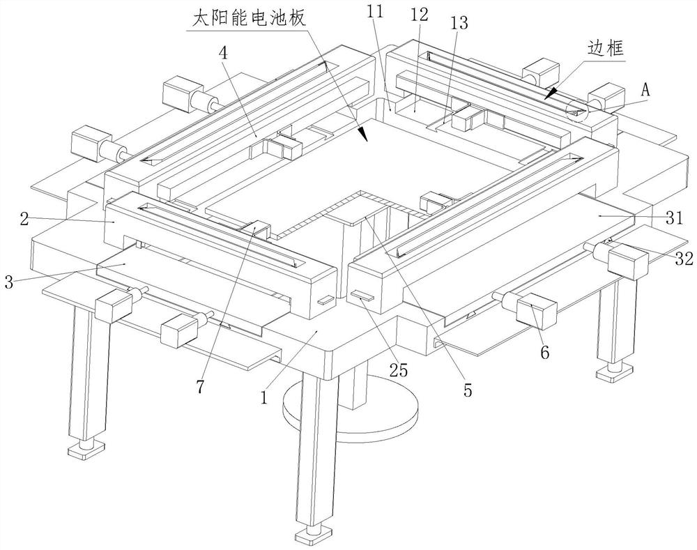
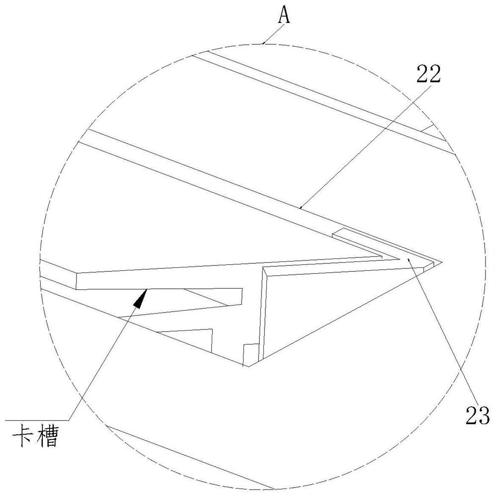
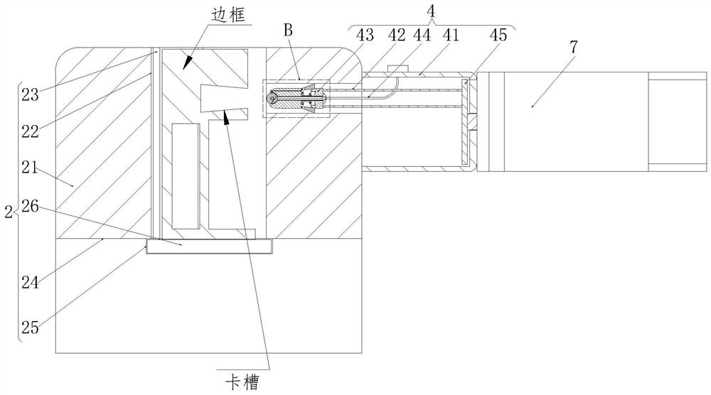
[0034] Such as Figure 1 to Figure 7As shown, a solar cell module assembly device includes a worktable 1, an outer frame placement mechanism 2, an assembly mechanism 3, a gluing mechanism 4, a support table 5, an electric push rod A6 and an electric push rod B7, and the worktable 1 A rectangular hole 11 is provided at the center of the top of the table top, and movable grooves 12 are provided on the outer walls around the work surface 1, and the movable grooves 12 and the rectangular holes 11 are connected to each other. The top of each movable groove 12 is provide...


PUM


Abstract

The invention relates to a solar cell module assembling device and an assembling method thereof. The solar cell module assembling device comprises a workbench surface, outer frame placing mechanisms, an assembling mechanism, gluing mechanisms, a supporting table, an electric push rod A and electric push rods B. A rectangular hole is formed in the center of the top of the workbench surface, and movable grooves are formed in the outer walls of the periphery of the workbench surface; mutual communication between the movable grooves and the rectangular hole is realized. The top of each movable groove is provided with a trapezoidal limiting groove, one outer frame placing mechanism is arranged at the position, located over each movable groove, of the top of the workbench surface, the gluing mechanism is installed on one side of each outer frame placing mechanism, and the electric push rod B is installed on one side of each gluing mechanism; and the assembling mechanism is arranged under the outer frame placing mechanisms, one end of the assembling mechanism is connected with the electric push rod A, and a supporting table is arranged in the center of the rectangular hole. The solar cell module assembling device has the characteristics of being high in assembling precision and rapid in gluing, and is high in gluing uniformity and low in glue waste rate.

Description

technical field [0001] The invention relates to the technical field of solar cells, in particular to a solar cell component assembly device and an assembly method thereof. Background technique [0002] Solar cells, also known as solar chips or photovoltaic cells, are photoelectric semiconductor sheets that use sunlight to generate electricity directly. As long as it is illuminated by light that meets certain illumination conditions, it can output voltage instantly and generate current when there is a loop. It is called solar photovoltaic in physics. A solar cell is mainly composed of a solar panel, a frame and a junction box. Since the solar panel, frame and junction box are all produced independently, when the components are produced, they need to be assembled. Among them, the solar cell module assembly device is one of them, which is mainly used for assembling between the frame and the solar cell panel. [0003] However, the solar cell module assembling device in the c...

Claims


Application Information

Patent Timeline
Patent Type & Authority Applications(China)
IPC IPC(8): H01L31/048H01L31/18
CPCH01L31/048H01L31/18Y02P70/50
Inventor 谭鑫刘波徐柳青
Owner 江苏悦阳光伏科技有限公司
Why Eureka
Try Eureka