Eureka AIR delivers breakthrough ideas for toughest innovation challenges, trusted by R&D personnel around the world.

A small hand-held laser head for laser cleaning

A laser cleaning and hand-held technology, which is applied in the direction of cleaning methods and appliances, chemical instruments and methods, etc., can solve problems such as damage, troublesome operation, and affecting equipment quality, so as to improve the cleaning effect and avoid secondary oxidation.

Active Publication Date: 2022-06-28
上海时颖激光科技有限公司
View PDF7 Cites 0 Cited by
  • Summary
  • Abstract
  • Description
  • Claims
  • Application Information

AI Technical Summary

Problems solved by technology

[0003] At present, hand-held portable laser cleaning is mostly used. The existing hand-held laser head usually includes a housing with a handle. One end of the housing is connected to the delivery tube for transporting the optical fiber, and the other end is equipped with an output head for outputting the laser beam. The output head There is a laser port formed on the output head, the opening size of the laser port is compatible with the model of the output head, and the corresponding output head can be replaced according to the equipment to be cleaned, which is troublesome to operate, and due to the diversification of the size of the equipment to be cleaned , the caliber of the laser port of the output head cannot fully adapt to the equipment to be cleaned. When the caliber of the laser port of the output head is larger than the size of the equipment to be cleaned, the range of the output laser is too large, and the excess laser will cause damage to other parts. damage, affecting the overall quality of the device

Method used


Image

  • A small hand-held laser head for laser cleaning
  • A small hand-held laser head for laser cleaning
  • A small hand-held laser head for laser cleaning

Examples


Embodiment

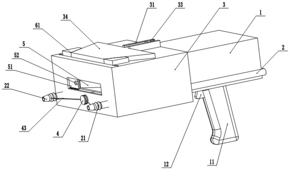
[0028] A small hand-held laser head for laser cleaning, such as Figures 1 to 6 As shown, it includes a housing 1, a control circuit and an optical element (not shown) are arranged in the housing 1, a grip handle 11 is installed at the bottom of the housing 1, and a grip handle 11 is installed on the grip handle 11 for controlling the output of the laser beam The control switch 12 is connected to the control circuit; the optical element is used for laser beam shaping and deflection, and the control circuit is used to control the beam deflection, and the laser beam is irradiated on the object to be cleaned to form a beam with a certain width, the beam Can be used to clean all kinds of stains on the surface of objects.

[0029] The optical elements include a collimating mirror, a focusing mirror, a reflecting mirror, a scanning mirror and a transparent lens. The above-mentioned collimating mirror, focusing mirror, reflecting mirror, scanning mirror and transparent lens are all a...


PUM


Abstract

The invention relates to the technical field of laser cleaning equipment, and discloses a small hand-held laser head for laser cleaning, which includes a casing and an output head, a laser port is formed on the output head, and a mounting cover is provided on the outer cover of the laser port. Both sides of the opening slide through a cover plate, the cover plate is fixedly connected with a connecting rod, and an elastic member is fixedly connected between the two connecting rods, and the top of the connecting rod runs through the installation cover and slides with the first chute of the installation cover; The top of the installation cover is slidably connected with a slider, the two sides of the slider are formed with a first guide surface, the top of the connecting rod is formed with a connection block, and a second guide surface is formed on the connection block; by sliding the slider, the two first guide surfaces are formed. One guide surface can be in sliding contact with two second guide surfaces respectively, and drive the two connecting rods to move oppositely or towards each other to drive the two cover plates to move oppositely or towards each other, so as to adjust the opening and closing of the laser port to adapt to equipment of different sizes Cleaning to avoid laser damage to other parts during the cleaning process.

Description

technical field [0001] The invention relates to the technical field of laser cleaning equipment, in particular to a small handheld laser head used for laser cleaning. Background technique [0002] Laser cleaning generally uses a high-speed scanning motor to scan the surface of the workpiece back and forth with a high-energy laser beam in a certain direction, so that the oil, rust or coating on the surface evaporates or peels off instantly, and quickly and efficiently removes attachments or coatings on the surface of the workpiece. , and then make the surface of the material achieve a clean process. [0003] At present, hand-held portable laser cleaning is mostly used. The existing hand-held laser head usually includes a case with a handle installed. One end of the case is connected to the conveying pipe for conveying the optical fiber, and the other end is equipped with an output head for outputting the laser beam. The laser port is formed on the output head, and the openin...

Claims


Application Information

Patent Timeline
Patent Type & Authority Patents(China)
IPC IPC(8): B08B7/00B08B13/00
CPCB08B7/0042B08B13/00
Inventor 刘海波
Owner 上海时颖激光科技有限公司
Why Eureka
Eureka Blog
Learn More