
Fiber bragg grating strain detection device

A detection device and fiber grating technology, which is applied to measurement devices, optical devices, instruments, etc., can solve the problems of inconvenience of different specifications of fiber gratings and reduced detection efficiency.

Active Publication Date: 2021-04-20
NO 59 RES INST OF CHINA ORDNANCE IND
View PDF23 Cites 0 Cited by
  • Summary
  • Abstract
  • Description
  • Claims
  • Application Information

AI Technical Summary

Problems solved by technology

Fiber Bragg grating needs strain detection in the actual production and processing process. The existing strain detection device is not convenient to control the detection feed rate for different specifications of fiber gratings, which reduces the actual detection efficiency; therefore, it is necessary to carry out the existing technology Improve

Method used


Image

  • Fiber bragg grating strain detection device
  • Fiber bragg grating strain detection device
  • Fiber bragg grating strain detection device

Examples


Embodiment 1

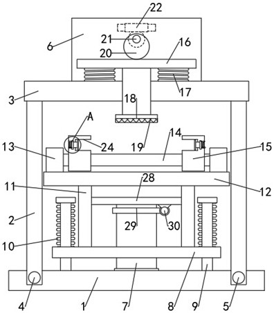
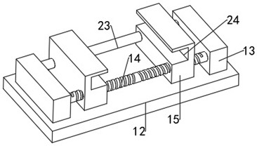
[0019] see Figure 1-3 , a fiber grating strain detection device, comprising a base 1, a support frame 2 is movably installed on the base 1, an end of the support frame 2 away from the base 1 is connected to a mounting seat 3, and the upper end surface of the mounting seat 3 is fixed with a Drive chamber 6, a pressure plate 16 is movable installed in the drive chamber 6, the cross section of the pressure plate 16 is T-shaped, the pressure plate 16 extends to the bottom of the mounting seat 3 and is connected with a pressure block 18, on the pressure block 18 A pressure sensor 19 is installed; a fixed seat 12 is movably installed on the base 1 , and a clamping mechanism is arranged on the fixed seat 12 to clamp the optical fiber grating to be tested. The clamping mechanism is located under the pressure block 18 .

[0020] Further, a pressure plate 16 is slidably installed in the drive chamber 6, and several vertical return springs 17 are evenly installed between the lower end s...

Embodiment 2

[0028] In order to make the base plate 8 rise and fall smoothly, this embodiment is improved on the basis of embodiment 1. The improvement is: the section of the guide rod 9 is T-shaped, and the guide rod 9 is located on the periphery of the upper end of the base plate 8. The guide spring 10 is used to improve the stability of the lifting of the substrate 8, which is convenient to use.


PUM


Abstract

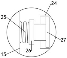
The invention discloses a fiber bragg grating strain detection device which comprises a base, a supporting frame is movably installed on the base, a mounting base is connected to the end, deviating from the base, of the supporting frame, and a driving chamber is fixed to the upper end face of the mounting base. According to the fiber bragg grating strain detection device, vertical feeding of the fixing base is controlled through a lifting lead screw, the distance between the fiber bragg grating and the pressurizing block is convenient to adjust, and therefore the fiber bragg grating strain detection device is suitable for detection of fiber bragg gratings of different specifications; an eccentric wheel is driven to operate through meshing of a worm wheel and a worm, the feeding amount of the pressurizing plate is conveniently controlled, and detection precision is improved; a limiting block is arranged in a limiting groove, so that the clamping force of the fiber bragg grating is convenient to control, and damage is avoided; through cooperation of a guide rod and a guide spring, the fixed seat operates stably and is convenient to adjust; in addition, the straight movement of the mounting base is controlled through the feeding screw rod, so that the relative positions of the pressurizing block and the fiber bragg grating are conveniently controlled, and multi-point detection is realized.

Description

technical field [0001] The invention relates to a detection device, in particular to a fiber grating strain detection device. Background technique [0002] Fiber grating is a kind of diffraction grating formed by axial periodic modulation of the refractive index of the fiber core by a certain method. It is a passive filter device. Because the grating fiber has small , can be embedded in smart materials, and its resonance wavelength is sensitive to changes in the external environment such as strain, refractive index, concentration, etc., so it has been widely used in the field of optical fiber communication and sensing. Fiber Bragg grating needs strain detection in the actual production and processing process. The existing strain detection device is not convenient to control the detection feed rate for different specifications of fiber gratings, which reduces the actual detection efficiency; therefore, it is necessary to carry out the existing technology Improve. Contents ...

Claims


Application Information

Patent Timeline
IPC IPC(8): G01B11/16
Inventor 何建新周漪王成章舒畅廖光萌佘祖新周堃朱玉琴李超杨小奎赵方超
Owner NO 59 RES INST OF CHINA ORDNANCE IND
Learn More